
Electrodes having electrode additive for high performance batteries and applications of same

a technology of additives and electrodes, applied in the field of batteries, can solve the problems of low ionic conductivity, low battery performance, and low production efficiency, and achieve the effects of improving thermal stability, rate and cycle performance of batteries, enhancing cationic transport, and alleviating interfacial resistan

Pending Publication Date: 2020-06-11
RGT UNIV OF CALIFORNIA +1
View PDF4 Cites 15 Cited by
  • Summary
  • Abstract
  • Description
  • Claims
  • Application Information

AI Technical Summary

Benefits of technology

This patent describes a way to make a type of material called porous coordination solids (also known as metal-organic frameworks) that can be used as additives in batteries to improve their performance. These materials can be mixed into battery electrodes and can help make the battery more stable, faster, and more durable. The process of making these additives is compatible with current battery manufacturing methods. The materials can also help the battery's electrolyte move more easily, which can make it more efficient. The result is a battery that can perform better and last longer.

Problems solved by technology

The long charging time, formidable cost and safety concern from intrinsic flammability of liquid electrolyte significantly retard the widespread adoption of electric vehicle and green energy technology.
Despite evident improvement in rate performance, this strategy compromises the tap density of electrode materials and it is relatively difficult for scaled up production.
Moreover, the safety issue of liquid electrolyte can be alleviated by using ceramic or polymer based solid electrolyte, while the insufficient ionic conductivity and challenging interfacial resistance fall short of commercial applications.
So far, seldom approach targeting industrial applications has been proposed to simultaneously resolve those key limitations existing in current batteries technologies.

Method used


Image

  • Electrodes having electrode additive for high performance batteries and applications of same
  • Electrodes having electrode additive for high performance batteries and applications of same
  • Electrodes having electrode additive for high performance batteries and applications of same

Examples


example 1

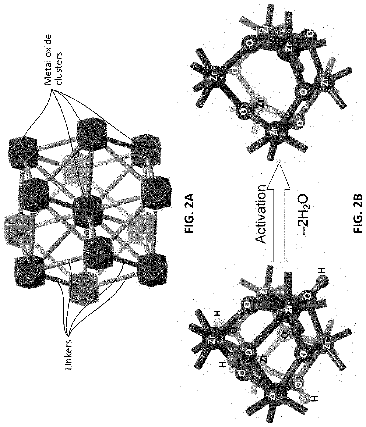
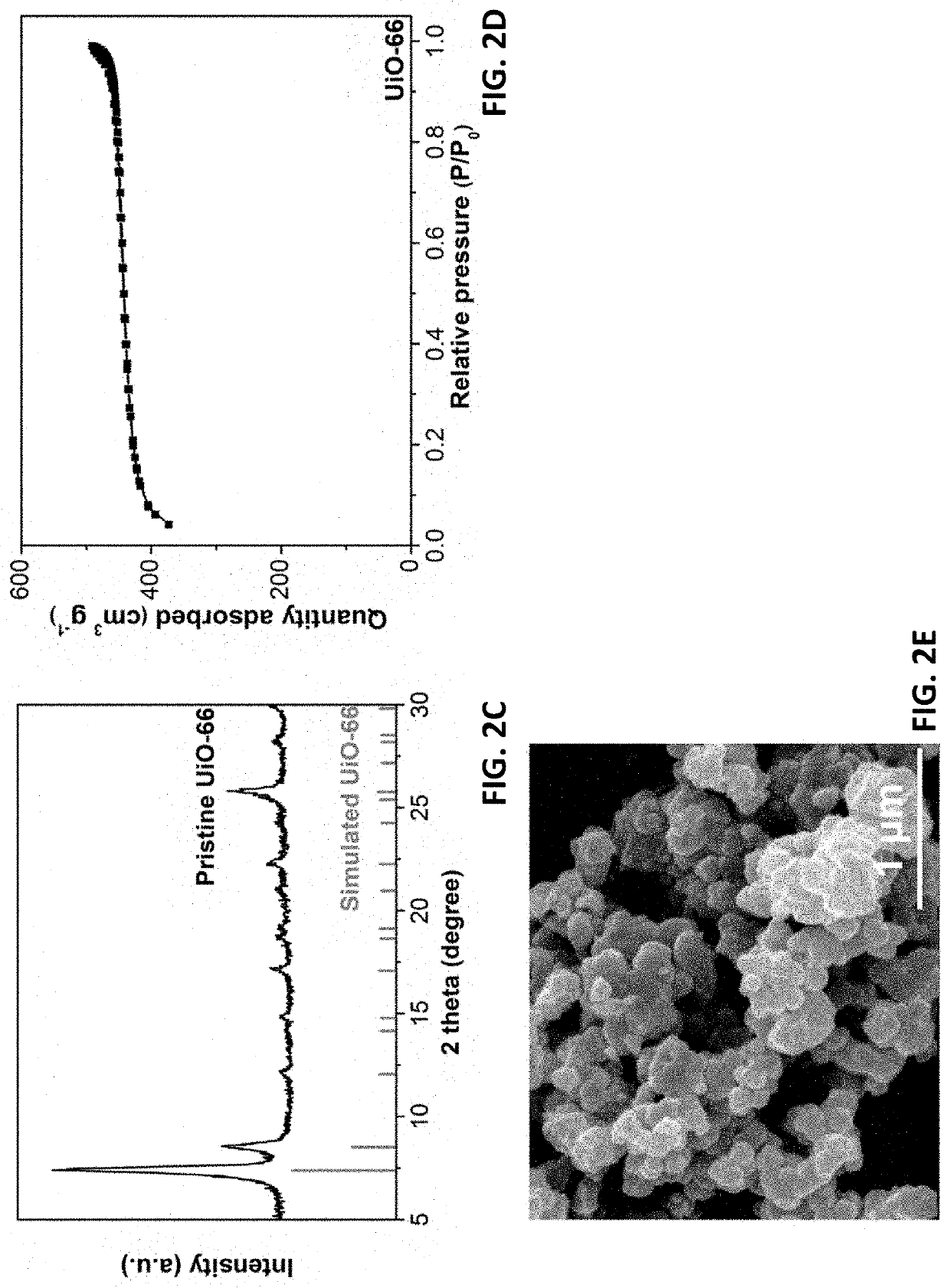
[0098]In this exemplary example, the synthesis of UiO-66 MOF includes the following steps. About 1.23 g of BDC ligand and about 1.25 g of ZrCl4 were dissolved in 100 mL of N,N-dimethylformamide (DMF) and about 50 / 10 mL of DMF / hydrochloric acid (37 wt % HCl, concentrated) mixture, respectively. These two fully dissolved solutions were combined and magnetically stirred for an additional about 30 min. The resulting transparent precursor solution was loaded in a tightly sealed glass vial and heated at about 150° C. for about 20 hours. Afterwards, the precipitate was separated from solvents by centrifugation and first washed by DMF three times (3×40 mL). Methanol exchange was performed on the DMF-washed sample over a period of about 3 days. The sample was replenished with fresh methanol twice a day (each for about 40 mL). Eventually the sample was dried at about 80° C. for about 1 day prior to further characterization.

[0099]As showed in FIG. 2C, the crystal structure was determined by X-...

example 2

[0104]Besides the NCM cathode, performances of typical anodes including graphite (C) and lithium titanate (Li4Ti5O12, LTO) with MOF additives were also explored. The MOF additive used here is exemplified while not restricted to UiO-66. The activated UiO-66 were homogeneously mixed with graphite / LTO, acetylene black (CB), polyvinylidene fluoride (PVDF) by a weight ratio of 5:87:5:2 in N-Methyl-2-pyrrolidone (NMP), afterwards the resulting electrode slurry were coated on copper current collect using a doctor blade. The ratio between electrode components is for demonstration purpose and optimized ratio is subject to engineering process. After two step drying at 80 and 170° C. under vacuum. The baked electrodes were calendered to thickness of 60 um with anode loading of 7.5 mg cm−2. For the reference electrodes without MOF, the graphite / LTO content is 92% instead while maintaining contents of CB and PVDF the same. Finally, the prepared electrodes were tailored into electrode disks with ...

example 3

[0105]To illustrate the superiority of MOF additives in a full cell configuration, NCM-C full cell (weight ratio between NCM and graphite is 15:7.5 mg cm−2) in coin cells were fabricated, where MOF additives were added to the cathode side. The combination of NCM and graphite is for demonstrative purposes and any combination of aforementioned electrodes is applicable. The cells were tested under 0.1 C, 1 C and 2 C between 2.5 to 4.2V for prolonged cycling. FIGS. 7A-7C show the cycling performance comparisons between the REF and HPE using NCM-C full cell configurations at different rates. The HPE (NCM-C) exhibit superior rate performance than the REF, especially at 2 C rate, the HPE can deliver almost one-fold higher specific capacity than the REF. The cycling results from full cells suggest that the improvement in terms of rate capability is more evident in full cell configuration, where the electric field might influence the concentration polarization of anion.

[0106]NCM-C full cells...


PUM

PropertyMeasurementUnit
pore sizeaaaaaaaaaa
temperatureaaaaaaaaaa
thicknessaaaaaaaaaa

Abstract

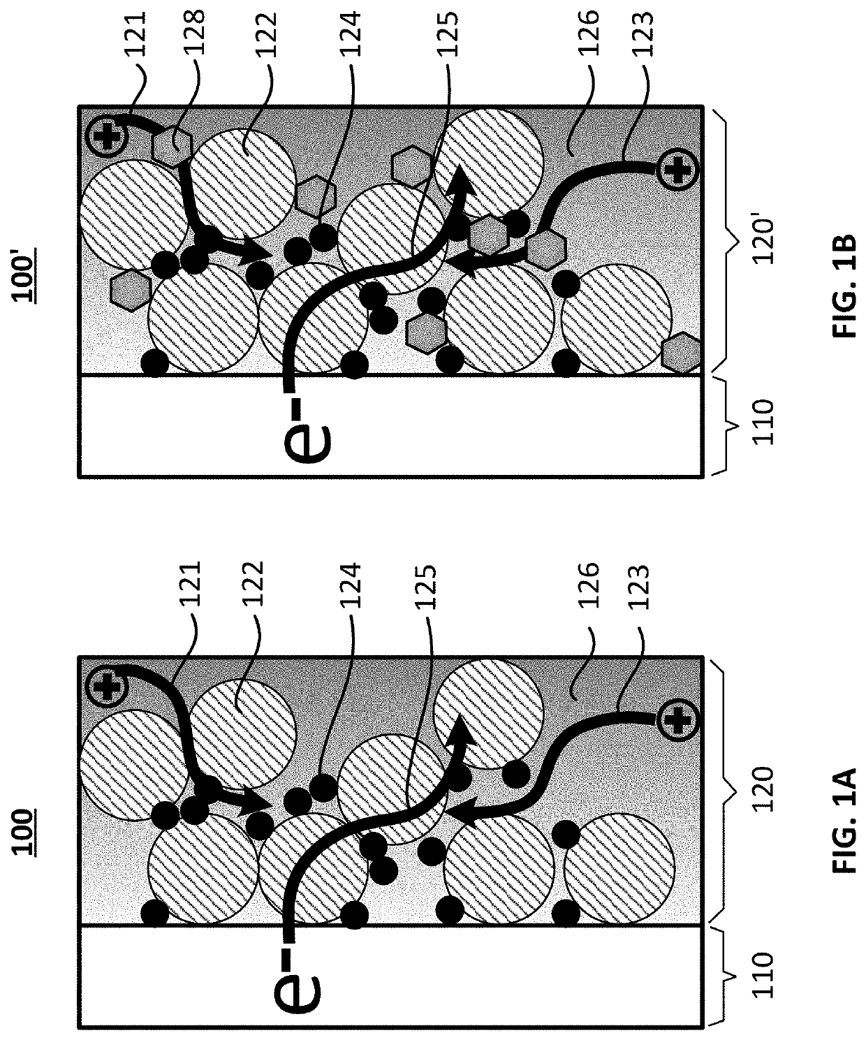
The invention provides a general type of porous coordination solids, metal-organic frameworks (MOFs), as an electrode additive to improve thermal stability, rate and cycle performances of batteries, and an electrode having the electrode additive. The incorporation of the MOF additive into the electrode is fully compatible with current battery manufacturing process. Activated MOF additive serves as an electrolyte modulator to enhance cationic transport and alleviates interfacial resistance by interacting liquid electrolyte with unsaturated open metal sites. Moreover, the flow-free liquid in solid configuration is realized by encapsulating liquid electrolyte into porous scaffold of MOF, which offers superior thermal stability.

Description

CROSS-REFERENCE TO RELATED PATENT APPLICATIONS[0001]This application claims priority to and the benefit of, pursuant to 35 U.S.C. § 119(e), U.S. provisional patent application Ser. No. 62 / 803,725, filed Feb. 11, 2019.[0002]This application is also a continuation-in-part application of U.S. patent application Ser. No. 15 / 888,223, filed Feb. 5, 2018, which claims priority to and the benefit of U.S. provisional patent application Ser. Nos. 62 / 455,752 and 62 / 455,800, both filed Feb. 7, 2017.[0003]This application is also a continuation-in-part application of U.S. patent application Ser. No. 15 / 888,232, filed Feb. 5, 2018, which claims priority to and the benefit of U.S. provisional patent application Ser. Nos. 62 / 455,752 and 62 / 455,800, both filed Feb. 7, 2017.[0004]This application is also a continuation-in-part application of U.S. patent application Ser. No. 16 / 369,031, filed Mar. 29, 2019, which itself claims priority to and the benefit of U.S. provisional patent application Ser. Nos...

Claims


Application Information

Patent Timeline
Patent Type & Authority Applications(United States)
IPC IPC(8): H01M10/42H01M4/62
CPCH01M4/625H01M4/623H01M10/4235Y02E60/10H01M4/0409H01M4/525H01M4/505H01M10/0525H01M10/0568H01M10/0569H01M2300/0037H01M10/54H01M4/485H01M4/483H01M4/5825H01M4/587H01M4/58Y02W30/84
Inventor XU, JIANGUOLU, YUNFENGSHEN, LI
Owner RGT UNIV OF CALIFORNIA
Learn More