
Battery module and method for manufacturing same

a battery module and battery technology, applied in the field of batteries, can solve the problems of metallurgical bonding not being possible, and achieve the effects of improving the reliability of the battery module, reducing the bonding time, and improving the productivity of the battery modul

Inactive Publication Date: 2019-11-28
PANASONIC INTELLECTUAL PROPERTY MANAGEMENT CO LTD
View PDF0 Cites 5 Cited by
  • Summary
  • Abstract
  • Description
  • Claims
  • Application Information

AI Technical Summary

Benefits of technology

The present patent improves the battery module by using a reliable method to join the lead plate to the battery cells' terminals, even between different types of metals. This improves the reliability of the battery module and reduces the bonding time, increasing productivity.

Problems solved by technology

However, in the case where a terminal of a battery cell is made of a material other than aluminum such as copper, copper alloy, or iron-based metal, since aluminum does not form an alloy layer with copper or iron, metallurgical bonding cannot be made.

Method used


Image

  • Battery module and method for manufacturing same
  • Battery module and method for manufacturing same
  • Battery module and method for manufacturing same

Examples


Embodiment Construction

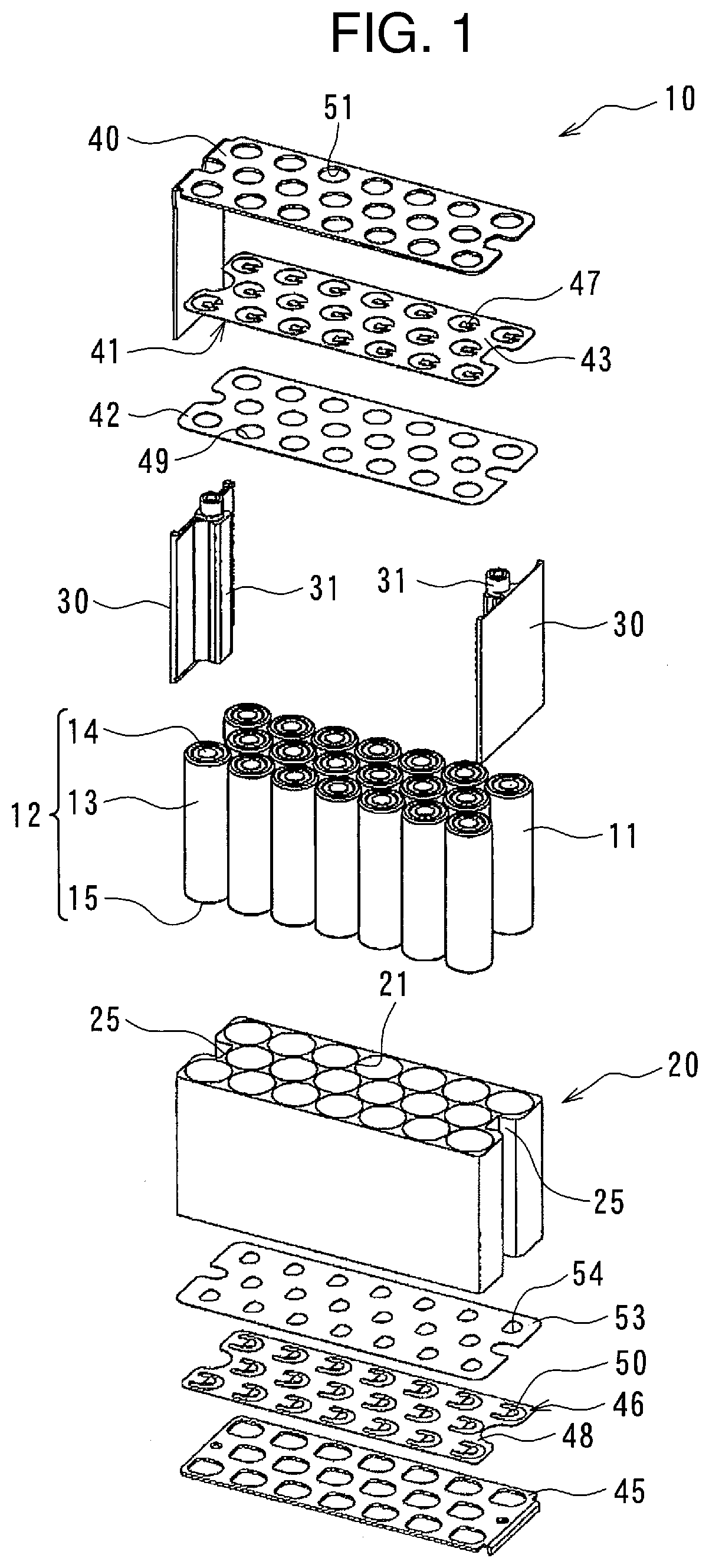
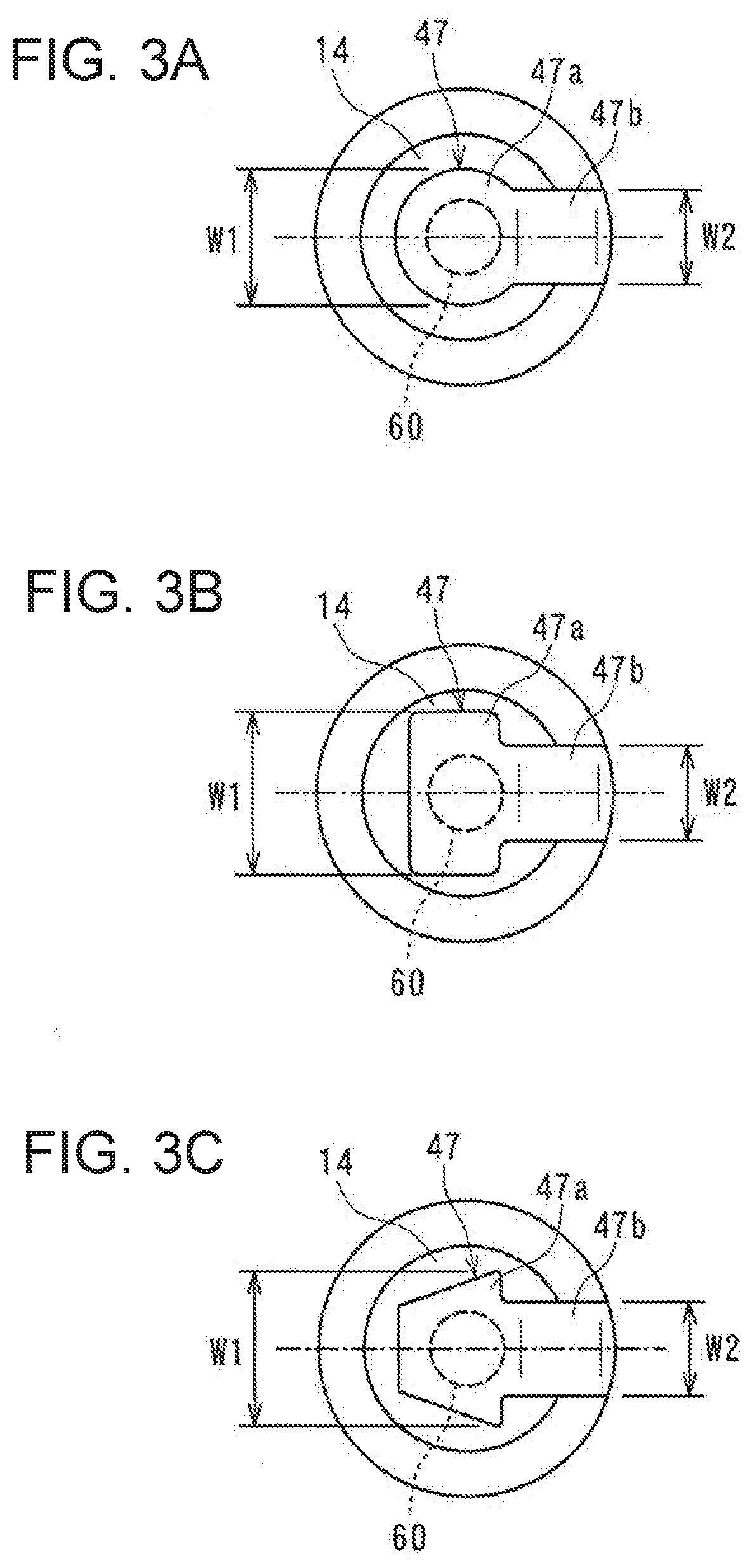
[0018]An exemplary embodiment of the present invention will now be described in detail with reference to the attached drawings. In the following description, specific shapes, materials, numerical values, directions, and other elements are examples shown to facilitate understanding of the present invention and may be changed as appropriate to suit uses, purposes, specifications, or other requirements. It is initially envisaged that when exemplary embodiments and modifications are included in the following description, some distinctive elements in the exemplary embodiments and the modifications are suitably combined and used.

[0019]Hereinafter, description will be given of a case where a battery cell is a cylindrical battery. However, the present disclosure may be applied to a battery module configured of a plurality of square-shaped battery cells connected with each other. Further, in the below description, a term “ultrasonic joining” is appropriately used instead of a typical term “u...


PUM

PropertyMeasurementUnit
surface roughnessaaaaaaaaaa
vibration frequencyaaaaaaaaaa
width W2aaaaaaaaaa

Abstract

A battery module includes a plurality of battery cells each having a terminal, and a lead plate having a lead part each of which is joined to the terminal of each of the battery cells to electrically connect the battery cells to each other. The lead part includes an aluminum thin plate having aluminum purity higher than or equal to 99.0%. Surface roughness Ra of a joining surface of the lead part to the terminal is less than or equal to 10 μm. The lead part is electrically connected to the terminal by solid-phase bonding.

Description

TECHNICAL FIELD[0001]The present disclosure relates to a battery module and a method for manufacturing the battery module.BACKGROUND ART[0002]Conventionally, a battery module configured of a plurality of battery cells electrically connected by a lead plate has been known. As a battery cell, a secondary battery such as a lithium ion battery or a nickel hydride battery is 15 preferably used. As a lead plate, a nickel thin plate or a copper thin plate is used. Besides it, for example, an aluminum thin plate may be used in consideration of weight, heating by a current flow, cost, and the like.[0003]A lead plate has a plurality of lead parts corresponding to the respective battery cells. For example, a lead part can be formed in a piece shape connected with the base plate of the lead plate in a cantilever state by means of punching applied to an aluminum thin plate in a plate shape. When the lead part formed as described above is connected to each of the terminals of the battery cells, e...

Claims


Application Information

Patent Timeline
Patent Type & Authority Applications(United States)
IPC IPC(8): H01M2/10H01M2/20H01M2/30B23K20/10H01M2/02H01M50/107H01M50/213H01M50/522H01M50/559H01M50/562
CPCH01M2/105H01M2/30H01M2/0202B23K20/10H01M2/204B23K2101/38B23K2101/36B23K20/24B23K20/26B23K20/2275B23K20/2333B23K20/2336B23K2103/10B23K2103/12B23K2103/18B23K2103/20Y02E60/10H01M50/522H01M50/559H01M50/562H01M50/213H01M50/107
Inventor OKUTANI, OOSESAKAMOTO, SHINICHI
Owner PANASONIC INTELLECTUAL PROPERTY MANAGEMENT CO LTD
Learn More