Laser welding of overlapping metal workpieces assisted by oscillating laser beam focal position

a laser beam and focal position technology, applied in welding/soldering/cutting articles, manufacturing tools, transportation and packaging, etc., to achieve the effect of improving strength and properties, reducing the power density and heat input of laser beams over time, and improving welding efficiency

Inactive Publication Date: 2019-07-25
GM GLOBAL TECH OPERATIONS LLC
View PDF3 Cites 6 Cited by
  • Summary
  • Abstract
  • Description
  • Claims
  • Application Information

AI Technical Summary

Benefits of technology

The patent describes a laser welding method for joining metal workpieces, specifically steel, aluminum, or magnesium workpieces, that overcomes challenges associated with traditional laser welding methods. The method involves cyclically varying the focal position of the laser beam during weld formation while maintaining a constant power level and travel speed. This allows for the formation of stronger and more properties laser weld joints without the need for gaps between the metal workpieces. The method also reduces the solubility of gaseous substances in the weld pool, which improves the strength and properties of the weld joint. Additionally, the method helps to release gases trapped within the molten material and minimize weld joint deficiencies such as spatter, blowholes, and undercut joints.

Problems solved by technology

The various metal workpieces included in each of the aforementioned workpiece stack-ups presents challenges when trying to join the workpieces together with a laser beam during assorted implementations of laser welding including remote laser welding and conventional laser welding.

Method used


Image

  • Laser welding of overlapping metal workpieces assisted by oscillating laser beam focal position
  • Laser welding of overlapping metal workpieces assisted by oscillating laser beam focal position
  • Laser welding of overlapping metal workpieces assisted by oscillating laser beam focal position

Examples


Embodiment Construction

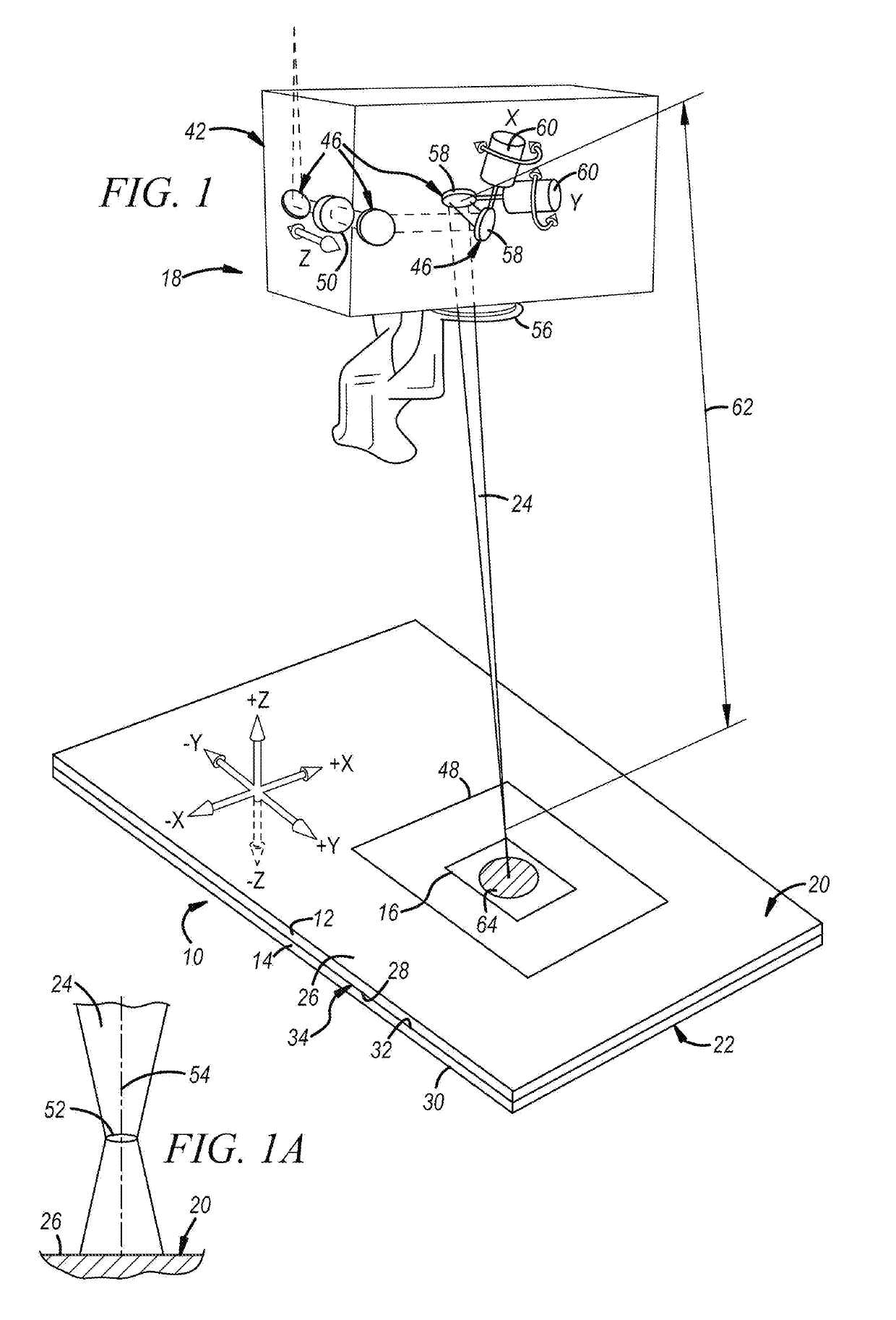
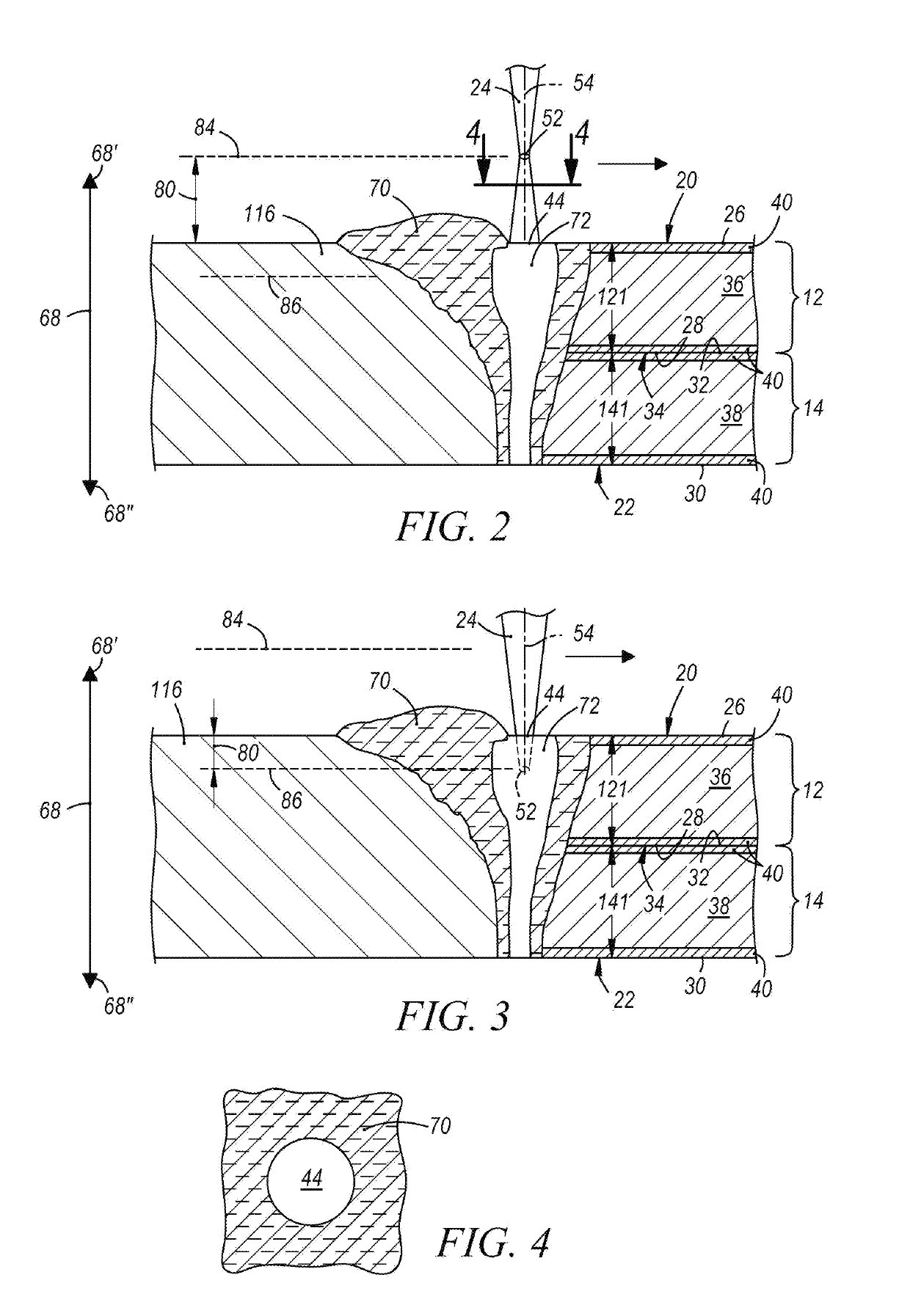
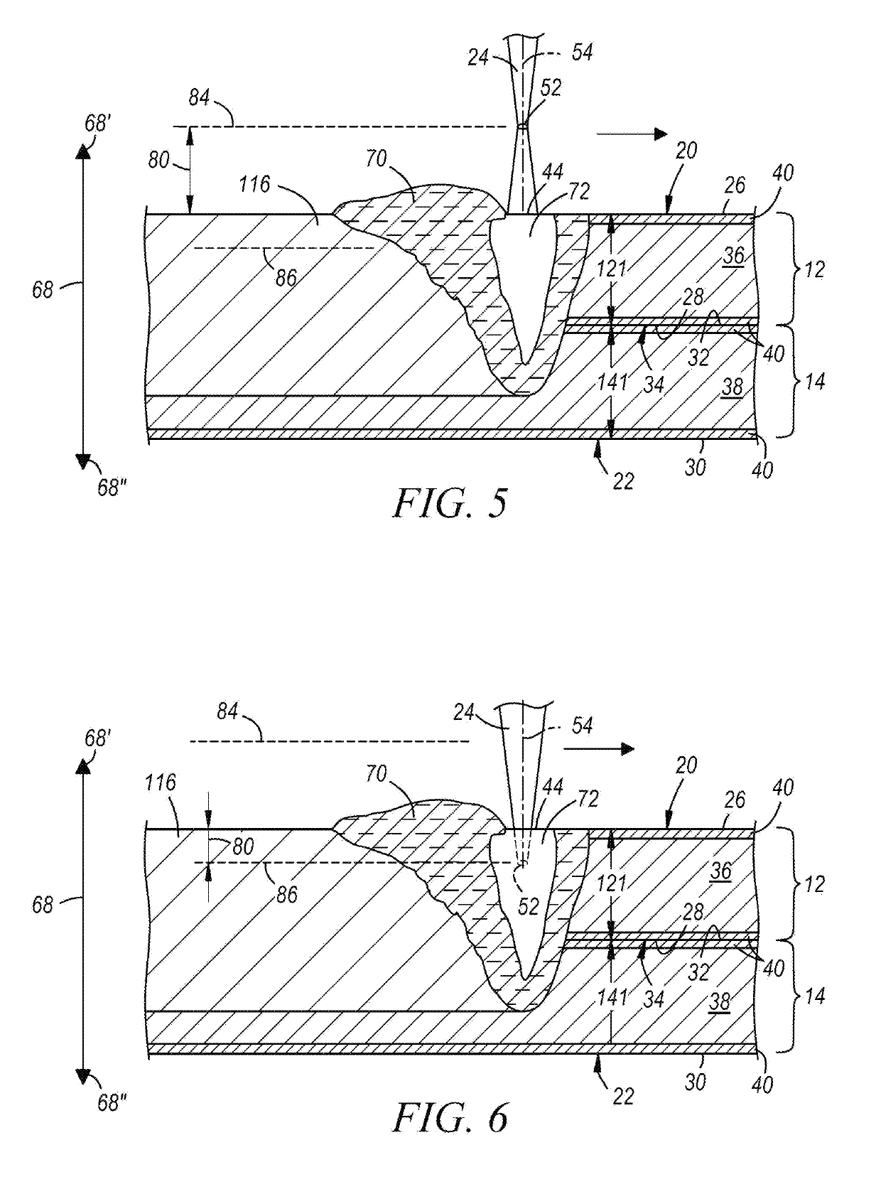
[0036]The disclosed method of laser welding a workpiece stack-up comprised of two or more overlapping metal workpieces involves forming a laser weld joint by oscillating a position of a focal point of a laser beam relative to a top surface of the stack-up along a dimension oriented transverse to a top surface at least part of the time while advancing the laser beam relative to a plane of the top surface along a beam travel pattern. Any type of laser welding apparatus, including remote and conventional laser welding apparatuses, may be employed to form the laser weld joint while oscillating the focal point of the laser beam and tracing the beam travel pattern. The laser beam may be a solid-state laser beam or a gas laser beam depending on the characteristics and compositions of the metal workpieces being joined and the laser welding apparatus being used. Some notable solid-state lasers that may be used are a fiber laser, a disk laser, a direct diode laser, and a Nd:YAG laser, and a n...


PUM

PropertyMeasurementUnit
Lengthaaaaaaaaaa
Lengthaaaaaaaaaa
Poweraaaaaaaaaa

Abstract

A method of laser welding a workpiece stack-up (10, 10′) that includes at least two overlapping metal workpieces (12, 150, 14) comprises advancing a beam spot (44) of a laser beam (24) relative to a top surface (20) of the workpiece stack-up (10, 10′) and along a beam travel pattern (66) to form a laser weld joint (64) that fusion welds the metal workpieces (12, 150, 14) together. While the beam spot (44) is being advanced between a first point (76) and a second point (78) of one or more weld paths (74) of the beam travel pattern (66), the position of a focal point (52) of the laser beam (24) is oscillated relative to the top surface (20) of the workpiece N stack-up (10, 10′) along a dimension (68) oriented transverse to the top surface (20).

Description

TECHNICAL FIELD[0001]The technical field of this disclosure relates generally to laser welding and, more particularly, to a method of laser welding together two or more overlapping metal workpieces in which all of the overlapping metal workpieces in the stack-up are steel workpieces, aluminum workpieces, or magnesium workpieces.BACKGROUND[0002]Laser welding is a metal joining process in which a laser beam is directed at a metal workpiece stack-up to provide a concentrated energy source capable of effectuating a weld joint between the overlapping constituent metal workpieces. In general, two or more metal workpieces are first aligned and stacked relative to one another such that their faying surfaces overlap and confront to establish a faying interface (or faying interfaces) that extends through an intended weld site. A laser beam is then directed towards and impinges a top surface of the workpiece stack-up. The heat generated from the absorption of energy from the laser beam initiat...

Claims


Application Information

Patent Timeline
IPC IPC(8): B23K26/244B23K26/04B23K26/082B23K26/08B23K26/322B23K26/073
CPCB23K26/244B23K26/048B23K26/082B23K26/0884B23K26/322B23K26/073B23K2101/34B23K2103/04B23K2103/10B23K2103/15B23K2101/006B23K2101/18
Inventor YANG, DAVIDTAO, WU
Owner GM GLOBAL TECH OPERATIONS LLC
Why Eureka
Try Eureka