
Catalyst part, and ventilation filter, ventilation plug, and lead-acid battery including the same

a technology of catalyst parts and ventilation filters, which is applied in the direction of secondary cell servicing/maintenance, sustainable manufacturing/processing, and separation processes. it can solve the problems of electrolyte solution leakage through the vent port, increase of gas pressure inside the battery, deformation and breakage of the battery, etc., and achieve the effect of reducing the gas release of an electrolyte solution and reducing the amount of electrolyte solution

Active Publication Date: 2019-05-09
W L GORE & ASSOC GK
View PDF0 Cites 2 Cited by
  • Summary
  • Abstract
  • Description
  • Claims
  • Application Information

AI Technical Summary

Benefits of technology

The present invention provides a catalyst part for a lead-acid battery that can reduce gas release from the electrolyte solution and prevent a decrease in the electrolyte solution levels. This results in a lead-acid battery with a longer lifespan.

Problems solved by technology

Otherwise, the gas pressure inside the battery would increase, which may lead to deformation and breakage of the battery.
Lead-acid batteries having a vent port, if tipped over, may cause an electrolyte solution to leak through the vent port.
In addition, in the case of an automotive lead-acid battery, an electrolyte solution may be shaken by the vibration of a running car and thereby cause the electrolyte solution to leak through the vent port.
Such leakage of gases or sprays through the vent port leads to a decrease in electrolyte solution.
The decrease in electrolyte solution results in an insufficient chemical reaction of battery and leads to a reduced charge capacity and discharge capacity.
It is described that a larger amount of oil tends to cause clogging to swell and deform a battery jar, whereas a smaller amount of oil tends to reduce the oxidation resistance of the separator to break the separator.

Method used


Image

  • Catalyst part, and ventilation filter, ventilation plug, and lead-acid battery including the same
  • Catalyst part, and ventilation filter, ventilation plug, and lead-acid battery including the same
  • Catalyst part, and ventilation filter, ventilation plug, and lead-acid battery including the same

Examples


examples

[0078]The present invention will now be described in more detail with reference to examples and comparative examples. The following examples, however, should not be construed as limiting the present invention.

[0079]As indicated in Table 1, catalyst parts were produced using materials in various combinations.

[0080]Hydrogen and oxygen were fed to each catalyst part, and the amount of moisture (water and water vapor) flowed back was measured. Based on the measurements, the flowback performance of the catalyst parts was determined.

[0081]A more specific test method will be described. To simulate a lead-acid battery, a chamber was provided, and the catalyst part produced was attached to the chamber. An electrolyte solution was not used. Instead, hydrogen gas (4 ml / min) and oxygen gas (2 ml / min) were fed from the inside of the chamber to the catalyst part. Oxygen and hydrogen were fed in two systems. In a feeding system (1), oxygen and hydrogen were continuously fed for 24 hours. In a feed...


PUM


Abstract

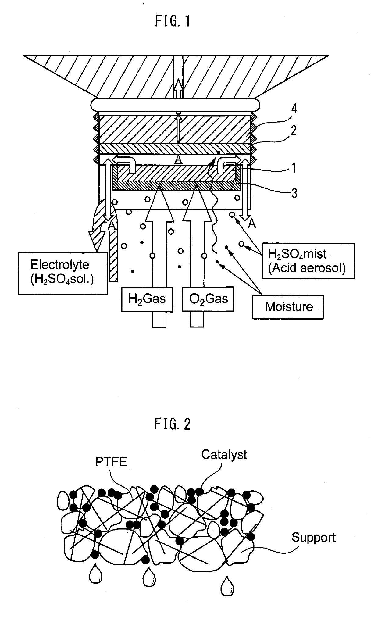
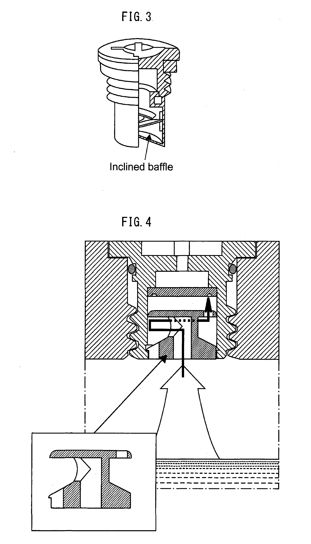
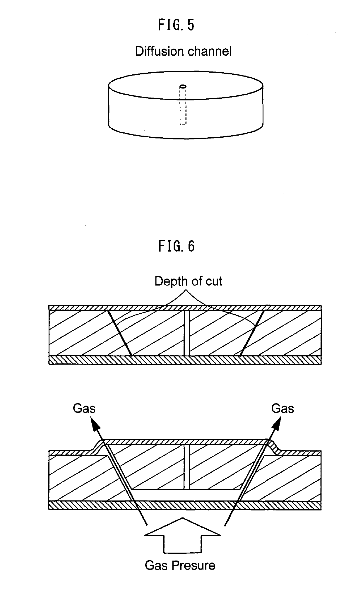
Provided is a catalyst part for a lead-acid battery, the catalyst part being capable of reducing gas release from an electrolyte solution and a decrease in electrolyte solution due to the leakage, thus providing a lead-acid battery having a long life. Also provided are a ventilation filter, a ventilation plug, and a lead-acid battery each including the catalyst part. A catalyst part for a lead-acid battery, including a catalyst layer including a catalyst to accelerate a reaction for generating water or water vapor from oxygen and hydrogen, and an arrangement through which at least part of the water or water vapor is condensed and / or flowed back to the inside of the battery.

Description

TECHNICAL FIELD[0001]The present invention relates to catalyst parts for lead-acid batteries and ventilation filters, more preferably to a catalyst part for a lead-acid battery, which catalyst part prevents the decrease in electrolyte solution and enables long life, a ventilation filter including the catalyst part, a ventilation plug including the catalyst part, and a lead-acid battery including the catalyst part.BACKGROUND ART[0002]Lead-acid batteries, in particular, automotive lead-acid batteries generally employ an open structure in which an electrolyte solution such as dilute sulfuric acid can freely flow. Lead-acid batteries having such a structure, when charged, generate oxygen and hydrogen gas and therefore need a vent port for discharging these gases. Otherwise, the gas pressure inside the battery would increase, which may lead to deformation and breakage of the battery. Lead-acid batteries having a vent port, if tipped over, may cause an electrolyte solution to leak through...

Claims


Application Information

Patent Timeline
IPC IPC(8): H01M10/52H01M2/12H01M2/36H01M10/12B01D53/86
CPCH01M10/523H01M2/1264H01M2/367H01M10/12B01D53/8671B01D2257/104B01D2257/108H01M10/121Y02E60/10H01M50/383H01M50/394Y02P70/50H01M50/35H01M50/392H01M50/668
Inventor KOBAYASHI, KOTARO
Owner W L GORE & ASSOC GK
Learn More