
Method For Depositing Protection Film Of Light-Emitting Element

a technology of light-emitting diodes and protection films, which is applied in the direction of chemical vapor deposition coatings, solid-state devices, coatings, etc., can solve the problems of difficult to realize a large size, difficult to prevent moisture and oxygen penetration, and difficulty in achieving large-scale sizes. , to achieve the effect of preventing moisture and oxygen penetration and reducing the processing time required for deposition

Active Publication Date: 2019-03-14
TES CO LTD
View PDF6 Cites 2 Cited by
  • Summary
  • Abstract
  • Description
  • Claims
  • Application Information

AI Technical Summary

Benefits of technology

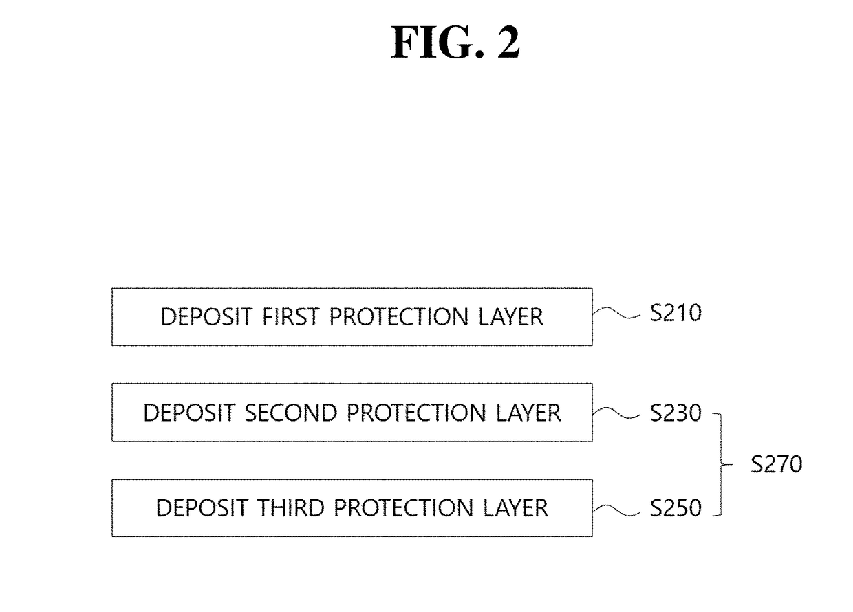
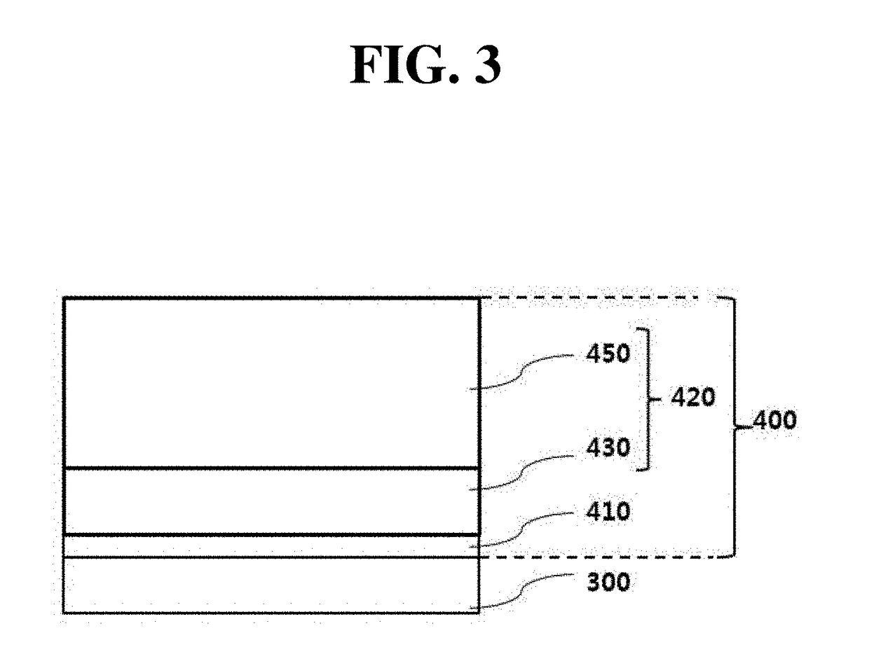
The present invention provides a method of depositing a protection film on LEDs using ALD and PECVD techniques. The first layer is deposited by ALD to ensure excellent step coverage and to reduce internal stress from the LED. The second and third layers are deposited by PECVD to achieve the benefits of both ALD and PECVD, such as low moisture transmissivity and flexible characteristics. The method allows for a thinner protection film and reduces processing time. This invention provides a multi-layered protection film that can prevent moisture and oxygen penetration for flexible display applications.

Problems solved by technology

However, the above OLED includes a structure including an organic thin film and an electrode and, thus, has a problem in that the OLED is rapidly degraded when external moisture, oxygen, or the like penetrates thereinto.
However, ALD advantageously has a low water vapor transmission rate (WVTR) but has a problem in that it is difficult to realize a large size and, in particular, throughput is remarkably low.
Furthermore, a protection film formed by PECVD has a problem in that its flexible characteristics are degraded due to a relatively very thick thickness.

Method used


Image

  • Method For Depositing Protection Film Of Light-Emitting Element
  • Method For Depositing Protection Film Of Light-Emitting Element
  • Method For Depositing Protection Film Of Light-Emitting Element

Examples


Embodiment Construction

[0035]Hereinafter, reference is made in detail to various embodiments, examples of which are illustrated in the accompanying drawings.

[0036]With regard to a structure of an organic light emitting diode (OLED), the OLED includes an injection-type thin film device with an emissive layer and a transport layer. Accordingly, the OLED is the same as an inorganic semiconductor in that they are a light-emitting diode using P-N junction but is different from a P-N junction-type light emitting diode (LED) in that the P-N junction-type LED is controlled by recombination via injection of minority carriers at a junction interface and the OLED is configured in such a way that all carriers involved in emitting light are injected from an external electrode. That is, a carrier injection-type light-emitting diode requires an organic material by which a carrier is easily injected and moved.

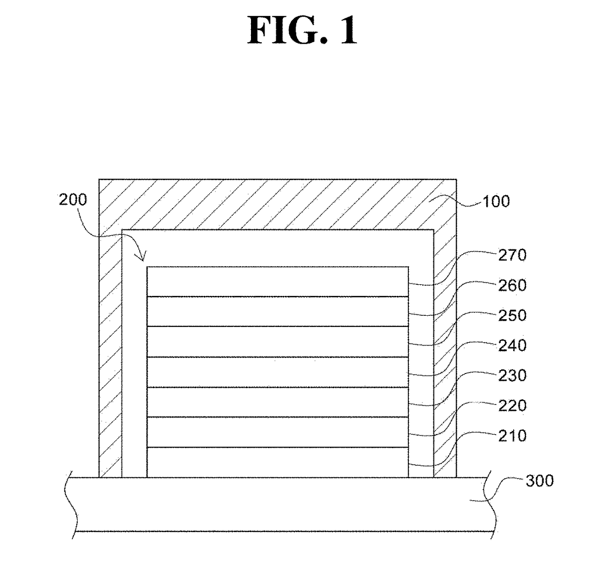
[0037]FIG. 1 is a side cross-sectional view showing a structure of an OLED.

[0038]Referring to FIG. 1, an OLED 200...


PUM

PropertyMeasurementUnit
Thicknessaaaaaaaaaa
Thicknessaaaaaaaaaa
Thicknessaaaaaaaaaa

Abstract

The present invention relates to a method for depositing a protection film of a light-emitting element, the method comprising the steps of: depositing a first protection layer on a light-emitting element of a substrate by means of the atomic layer deposition method; and depositing at least one additional protection layer on the first protection layer by means of the plasma-enhanced chemical vapor deposition method.

Description

CROSS-REFERENCE TO RELATED APPLICATIONS[0001]This application is a continuation application of International Application No. PCT / KR2017 / 005043 filed on May 16, 2017, which claims priority to Korean Application No. 10-2016-0060938 filed on May 18, 2016. The applications are incorporated herein by reference.TECHNICAL FIELD[0002]The present invention relates to a method of depositing a protection film of a light-emitting diode (LED), and more particularly, to a method of depositing a protection film in a so-called hybrid form including all of a protection layer deposited by atomic layer deposition (ALD) and a protection layer deposited by plasma enhanced chemical vapor deposition (PECVD).BACKGROUND ART[0003]Recently, with development of the information age, research has been actively conducted into a display device and, in particular, a light emitting diode (LED) display or an organic light emitting diode (OLED) has drawn attention.[0004]Such an OLED uses an organic material that auton...

Claims


Application Information

Patent Timeline
IPC IPC(8): C23C16/455C23C16/40C23C16/34H01L51/52H01L33/00H01L33/12
CPCC23C16/45553C23C16/401C23C16/403C23C16/345H01L51/5256H01L33/005H01L33/12C23C16/45555H10K59/8731C23C16/452C23C16/45525H01L33/02H01L2924/12041H01L2933/0025C23C16/505H01L33/44C23C16/45523H01L33/00H10K50/844H10K71/00H10K50/8445
Inventor LEE, HONG-JAEKIM, JONG-HWANSHIM, WOO-PILLEEYOON, SUNG-YEANLEE, DON-HEE
Owner TES CO LTD
Learn More