Self-Powered Bone Growth Stimulator

Inactive Publication Date: 2019-01-10
WEBSTER +1
View PDF0 Cites 2 Cited by
  • Summary
  • Abstract
  • Description
  • Claims
  • Application Information

AI Technical Summary

Benefits of technology

The invention is a system for promoting bone growth using a self-contained and durable nanogenerator device that is implantable and can produce electrical power. The system also includes an external signal generator that can be programmed to produce a mild mechanical pressure to stimulate bone growth. The nanogenerator device implanted at the site of the fracture or bone fusion produces a DC electrical current, which is sensed by the external signal generator and enhances the repair process. This system is effective, cost-efficient, and avoids the need for second surgeries to replace the battery of the generator or remove the device from the patient's body. The semi-invasive and biodegradable nature of the system also eliminates the need for additional surgeries.

Problems solved by technology

In addition, a significant number of nonunion fractures in long bones occur, which cause high physical morbidity and loss of quality of life.
There are several disadvantages to the present use of electrical stimulators to promote bone growth, including limited battery life (6-8 months for DC-based stimulators) and the need for a additional surgery to replace the battery or remove the implanted device at the end of therapy.

Method used


Image

  • Self-Powered Bone Growth Stimulator
  • Self-Powered Bone Growth Stimulator
  • Self-Powered Bone Growth Stimulator

Examples


example 1

on of Titania Nanotubes

[0034]Titanium foils (99.5% Ti, 0.25 mm thick, annealed) and platinum meshes were purchased from Alfa Aesar. Other chemicals were purchased from Sigma-Aldrich or Fisher Scientific. Ti foils were cut into 2.5 cm×2.5 cm squares and were cleaned with acetone, 70% ethanol, and deionized water (Milli-Q water) separately, each for 15 minutes. Then, the cleaned Ti foils were etched for 1 minute with a solution containing nitric acid solution (1.5% by weight) and hydrofluoric acid (1.5% by weight) to remove the naturally occurring oxide layer.

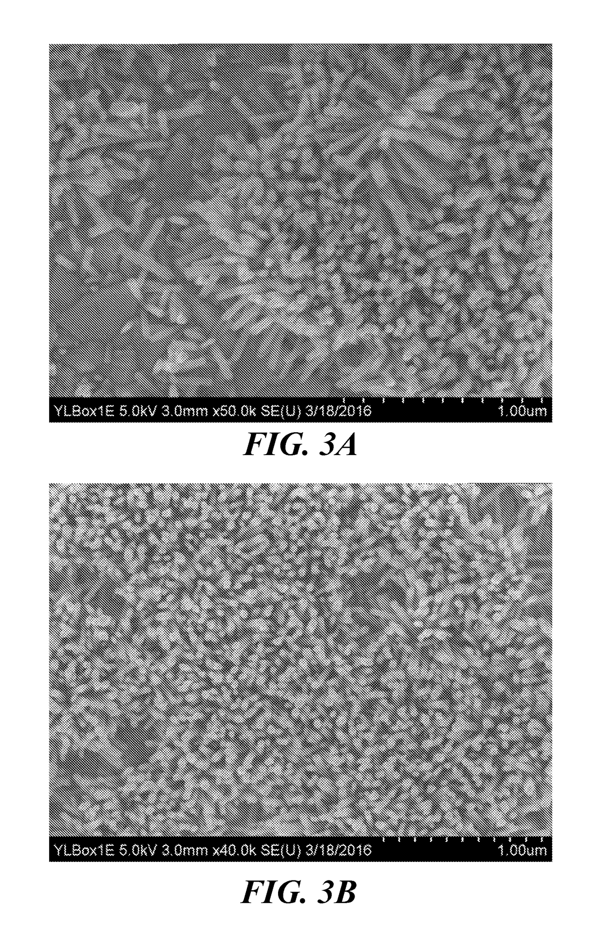
[0035]The Ti foils were then anodized using a two-electrode configuration, with a Pt mesh serving as the cathode and a Ti foil serving as the anode. One side of each of the Ti and Pt electrodes was immersed in an electrolyte solution consisting of 1% HF, while the other side of each electrode was connected to a DC power supply through copper wires. Anodization proceeded for 10 minutes at 20 V, during which titania nanotubes were ...

example 2

of ZnO Nanowires on Titania Nanotube Substrates

[0036]Zinc oxide nanowires were synthesized on anodized titanium substrates of Example 1 by two different methods. For either method, the substrate first was ultrasonically cleaned in acetone followed by ethanol and de-ionized water for five minutes in each solvent at room temperature, followed by drying under a nitrogen stream for 5 minutes at room temperature.

[0037]Method 1

[0038]Commercial zinc oxide nanoparticles (Nanophase Technologies Inc.) were seeded onto a substrate surface containing titania nanotubes via spin coating of a well agitated ethanolic solution containing 10 mM of zinc acetate dihydrate and polyvinylpyrrolidone. Following the spin coating process, the seeded substrate was annealed in air within a furnace at 200° C. for 120 minutes.

[0039]Method 2

[0040]Zinc carbonate nanoparticles were precipitated onto a titania substrate containing titania nanotubes by combining 1M zinc nitrate and 1M ammonium carbonate in an aqueous...

example 3

ZnO Nanowire-Generated Potential on Osteoblast Growth

[0042]Osteoblasts were grown on substrates (either pure Ti, anodized Ti with nanotubes, or anodized Ti with ZnO nanowires grown out of the titania nanotubes) for up to 5 days with mechanical stimulation. Mechanical stimulation was applied to the piezoelectric ZnO nanowires via an ADMET mechanical testing system to generate an electrical potential, whose influence on cell proliferation was tested.

[0043]Human osteoblasts obtained from PromoCell, Heidelberg, Germany, were used at population numbers less than ten for all cell experiments. Cells were cultured in Eagle's Minimum Essential Medium (EMEM; ATCC) supplemented with 10% fetal bovine serum (FBS; Sigma-Aldrich) and 1% penicillin / streptomycin (P / S; Gibco) or Dulbecco's Modified Eagle Medium (DMEM; ATCC) supplemented with 10% FBS and 1% P / S. The cells were seeded onto the ZnO nanowire / TiO2 nanotube substrates at a density of 5000 cells / cm2 and were allowed to grow for 1, 3, or 5 d...


PUM


Abstract

Devices, systems, and methods for therapies involving the application of an electrical signal within the body of a subject involve the use of an implanted piezoelectric nanogenerator to provide a self-generated electrical signal without the use of batteries. The electrical signal stimulates healing of a tissue, such as bone, or provides pain relief by inhibiting neuronal pain signals. An external signal generator induces mechanical stress in an implanted piezoelectric nanomaterial, which produces the electrical signal.

Description

BACKGROUND[0001]A large number of people suffer from neck and back pain due to arthritis and degenerative diseases. Approximately 432,000 spinal fusions are performed in the United States annually. In addition, a significant number of nonunion fractures in long bones occur, which cause high physical morbidity and loss of quality of life. While the body has its own natural healing process, it sometimes needs enhancement to function more effectively. Preclinical and clinical results show a promising therapeutic role for the use of electrical stimulators in bone healing, which operate by applying a stabilized electric current to the site of fracture or spinal fusion.[0002]There are several disadvantages to the present use of electrical stimulators to promote bone growth, including limited battery life (6-8 months for DC-based stimulators) and the need for a additional surgery to replace the battery or remove the implanted device at the end of therapy. Thus, there is a need for improved...

Claims


Application Information

Patent Timeline
IPC IPC(8): A61N1/32A61F2/44A61N1/02A61N1/36A61N1/20H01L41/113
CPCA61N1/326A61F2/44A61N1/025B82Y30/00A61N1/205H01L41/113B82Y5/00A61N1/36071H10N30/30
Inventor WEBSTERKUMARAKURU, HARIDAS
Owner WEBSTER
Why Eureka
Try Eureka