
High flux, chlorine resistant coating for sulfate removal membranes

a sulfate removal membrane, high flux technology, applied in the direction of membranes, specific water treatment objectives, reverse osmosis, etc., can solve the problems of membranes no longer preferred, membranes showing some deficiencies, and prone to hydrolysis in very high or very low ph, so as to improve chlorine resistance and increase the flux of membranes

Active Publication Date: 2018-12-27
TELEDYNE SCI & IMAGING
View PDF0 Cites 15 Cited by
  • Summary
  • Abstract
  • Description
  • Claims
  • Application Information

AI Technical Summary

Benefits of technology

This patent describes a coating that improves the performance of filtration membranes by increasing the flow of water through the memb struggles to resist chlorine, a common chemical used in water treatment. The coating includes a hydrophilic polymer, a surfactant, and charged compounds with sulfonate and amine functionalities. The coating is applied to the membrane while it is still in its final form, making it easy to treat existing membranes. The coating improves membrane performance without changing the manufacturing process.

Problems solved by technology

While this membrane is still used, it is prone to hydrolysis in either very high or very low pH solutions.
Since many cleaning solutions have either a high or a low pH, these membranes are no longer preferred.
However, known membranes exhibit some deficiencies, such as a low permeability and lack of resistance to chlorine in the feed water.
If the coating is thin enough, it dissolves with time and the higher permeability is lost.
If the coating is thick and more crosslinked, the resistance to permeability presented by the coating becomes an issue.
The comparatively low flux results in the need for a large membrane surface area when designing treatment plants, resulting in high capital cost.
Given that chlorine is a widely used, highly effective cleaning agent and inexpensive biocide, this presents a significantly technical deficiency.

Method used


Image

  • High flux, chlorine resistant coating for sulfate removal membranes
  • High flux, chlorine resistant coating for sulfate removal membranes

Examples


example 1

Counter Example 1

[0034]After measurement of the flux and rejection, an uncoated membrane coupon is rinsed with DI water and partially dried at room temperature. Separately a buffer solution is prepared by dissolving 0.52% tris(hydroxymethyl) aminomethane (Tris) in water and adjusting to pH8 with dilute HCl. To the buffer solution, 25.0 gm of Tris buffer solution is added to 26.2 gm of surfactant mixture. The mixture is stirred vigorously for about 1 minute, until a homogeneous viscous mixture is formed. The liquid is poured onto the partially dried membrane coupon and allowed to spread to form a thin layer. After sitting for 1 hour, the coated membrane coupon is immersed in a 32 gm / L aqueous NaCl solution overnight. The coupon is removed from the liquid and rinsed with DI water to remove excess coating.

[0035]The coupon is next immersed in a solution of 62 ppm NaOCl in pH10 NaHCO3 / Na2CO3 buffer solution for 20 hours to give a NaOCl exposure of 1240 ppm-hr. The coupon is then rinsed a...

example 3

Counter Example 3

[0042]After measurement of the flux and rejection, an uncoated membrane coupon is rinsed with DI water and partially dried at room temperature. The coupon is immersed in a solution of 0.3% benzopurpurin-4B at room temperature for 70 hours, then rinsed with DI water and soaked in 2 g / L NaCl overnight, then re-tested. Table 4 shows the performance of an uncoated membrane and the performance of the same membrane after coating.

TABLE 4SulfateChlorideRatio ofFluxSulfateinChlorideinsulfate(Gph / in feedproductin feedproductto chlorideMembranem2)(ppm)(ppm)(ppm)(ppm)rejectionUncoated14.626285419503172478.47Coated9.55262971190461778814.72

[0043]A large reduction in flux accompanied by reduction in sulfate reduction is seen when the membranes are modified only with the dye and nothing else.

example 2

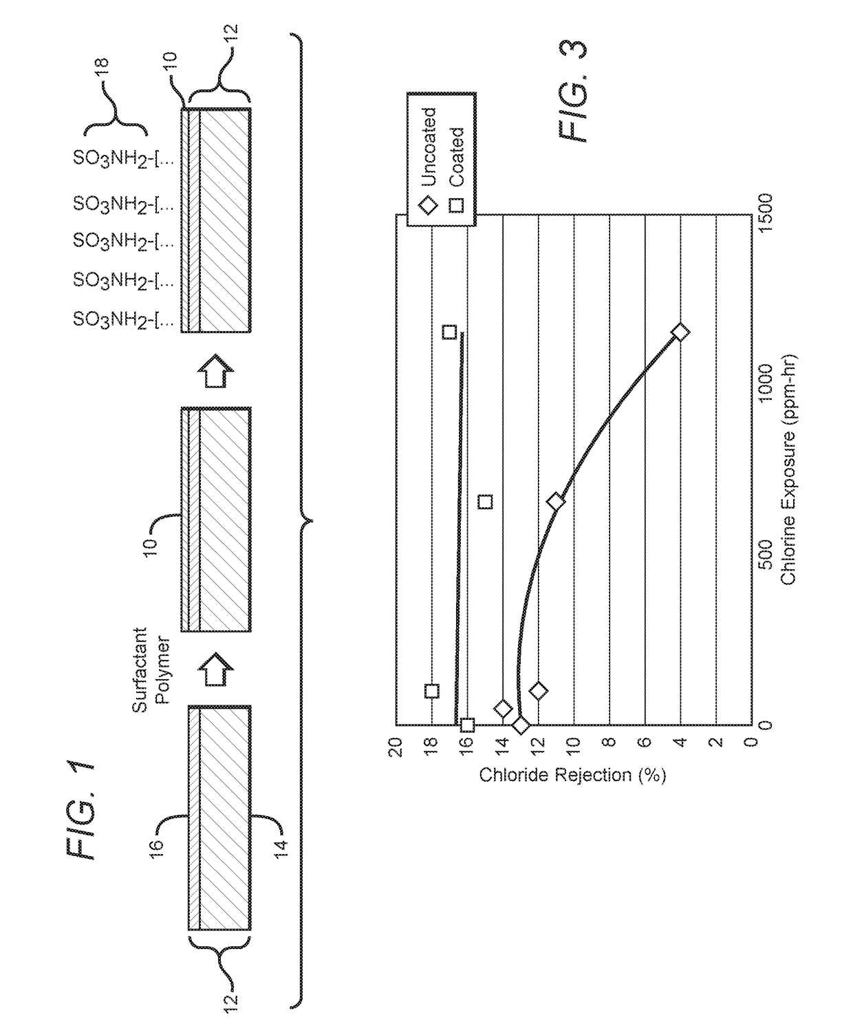
[0044]A membrane coupon as coated in Example 1, and an uncoated membrane coupon were both exposed to a solution of sodium hypochlorite (household bleach) for extended periods of time. The bleach containing solution was permeated through the membrane during the exposure period. Chloride rejection was measured for both membranes during various times and used to understand the effect of bleach on membrane properties. Typically, the chloride rejection of a membrane suffers (becomes lower) due to exposure to chlorine. The chloride rejection vs. the exposure as measured in ppm-hrs is shown in FIG. 3. The uncoated membrane shows large reduction in chloride rejection at 1150 ppm-hrs of exposure, whereas the chloride exposure of the coated membrane does not change.


PUM

PropertyMeasurementUnit
wt %aaaaaaaaaa
thicknessaaaaaaaaaa
thicknessaaaaaaaaaa

Abstract

A filtration membrane coating comprising a hydrophilic polymer, a surfactant, and one or more charged compounds, each containing one or more sulfonate functionalities and one or more linkable functionalities selected from the group consisting of amine, monochlorotriazine, and dichlorotriazine. The hydrophilic polymer and surfactant form a thin primer layer which is also superhydrophilic. The primer layer improves flux, and enables improved adhesion of the one or more charged compounds, which form a charged dye layer on top of the primer layer when enhances rejection of charged divalent ions. The coating can be applied while the membrane is packaged in its final form, such as in a spiral wound or other configuration.

Description

BACKGROUND OF THE INVENTIONField of the Invention[0001]This invention relates generally to filtration membranes, and more particularly to filtration membranes used for removing sulfate ions from seawater.Description of the Related Art[0002]Microfiltration (MF), ultrafiltration (UF), nanofiltration (NF), and reverse osmosis (RO) are pressure-driven separation processes used to remove a broad range of neutral or ionic molecules from fluids. Of these, nanofiltration membranes are used for removing sulfate ions from seawater prior to reservoir injection in the oil and gas industry. The NF membranes pass dissolved monovalent ions, while maintaining high rejection of dissolved divalent ions. By contrast, reverse osmosis membranes remove most dissolved ions (mono+divalent) and are used in desalination.[0003]One of the first industrially utilized membranes capable of removing all dissolved ions from water was the cellulose acetate membrane developed by Loeb and Sourirajan (U.S. Pat. Nos. 3,...

Claims


Application Information

Patent Timeline
Patent Type & Authority Applications(United States)
IPC IPC(8): B01D69/02B01D69/12B01D71/56B01D71/82B01D65/08B01D61/02C02F1/44B01D67/00
CPCB01D69/02C02F2103/08B01D71/56B01D71/82B01D65/08B01D61/027C02F1/442B01D67/0088B01D67/0093B01D2323/02B01D2323/40B01D2323/48B01D2325/20B01D2325/30B01D2325/36B01D69/12B01D2325/28C02F2101/101C02F2303/22B01D2323/216B01D2323/217B01D2323/21815B01D2323/21834B01D2321/167B01D69/1216B01D67/00931C09D5/1687C09D101/28C09D105/00C09D105/12B01D2325/04C08K5/005
Inventor STRAUSS, DENNIS R.GANGULI, RAHULLIAO, TEN-LUEN T.MEHROTRA, VIVEKVERBEEK, PAULUS HENRICUS JOHANNESKREBS, THOMAS
Owner TELEDYNE SCI & IMAGING
Learn More