
Method for additive production, component, and apparatus for additive production

Active Publication Date: 2018-11-15
SIEMENS ENERGY GLOBAL GMBH & CO KG
View PDF0 Cites 0 Cited by
  • Summary
  • Abstract
  • Description
  • Claims
  • Application Information

AI Technical Summary

Benefits of technology

The present invention relates to a method for producing a component by heating and cooling the component to achieve a microstructure that is low in defects, favorable for an application of the component, and solidified molten powder. The invention also aims to reduce temperature gradients and generate a uniform temperature profile in the component by implementing local heating and cooling devices. The resulting component has reduced density of structural defects, imperfections, and grain boundaries, and advantageously reduced residual stresses and evidence of warping and bonding defects.

Problems solved by technology

In particular in the case of projecting structures of the component, this in a localized manner can lead to high temperatures and thus to damage to the component or even to the production installation or apparatus.
In the worst case, warping and / or collisions with one of the coating apparatuses of the system could arise, for example.
To date, for example, the material quality of components produced by casting methods, in particular in the production of turbine blades, has not yet been able to be achieved by additive methods.
In particular, the structure of additively produced components in terms of warping, grain sizes, and / or structural defects is unfavorable as compared to structures which are produced or producible by casting, a crystal growing method, or another method for targeted solidification.

Method used


Image

  • Method for additive production, component, and apparatus for additive production
  • Method for additive production, component, and apparatus for additive production
  • Method for additive production, component, and apparatus for additive production

Examples


Embodiment Construction

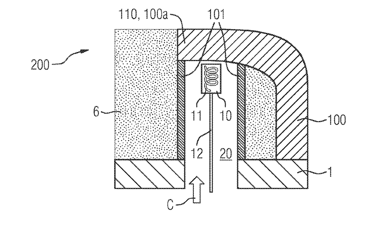
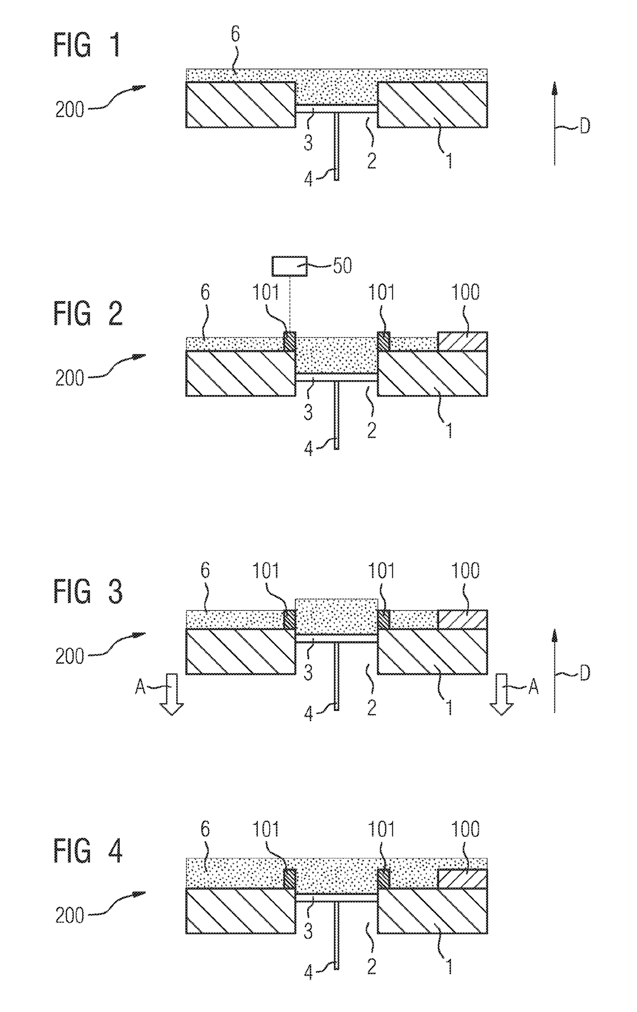
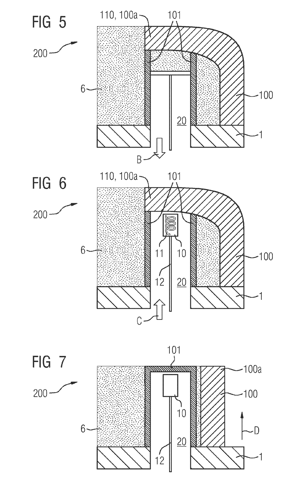
[0045]FIG. 1 schematically shows at least a part of an apparatus 200 for the additive production of a component 100 (cf. FIGS. 2 to 7). The component 100 is in particular a component having a complex structure or contour, or an elongate and / or curved component.

[0046]The apparatus 200 is in particular an apparatus or a system for an additive, for example powder-bed-based production method such as a method for selective laser melting (SLM) and / or electron beam melting (EBM).

[0047]The apparatus 200 comprises a component platform 1. The component platform 1 can be a substrate on which a workpiece or a component is constructed layer-by-layer in the context of the additive production. The component platform in commonplace respective apparatuses is usually and advantageously capable of being lowered relative to further components of the apparatus, for example to an exposure or laser apparatus. The component platform 1 has an opening 2. The opening 2 in an exemplary manner is disposed centr...


PUM

PropertyMeasurementUnit
Temperatureaaaaaaaaaa
Densityaaaaaaaaaa
Aspect ratioaaaaaaaaaa

Abstract

A method for additive production of a component, which includes the additive construction of the component on a component platform having an opening, wherein, during the first part of the additive construction of the component an auxiliary structure is produced additively around the opening of the component platform. The method further includes the introduction of a device through the opening into a cavity defined by the auxiliary structure, wherein, during a second part of the additive construction, following the first part of the additive construction, properties of the component to be produced are influenced and / or measured by the device. A component is produced by the method and an apparatus for the additive production of the component, includes the component platform having the opening and the closure.

Description

CROSS REFERENCE TO RELATED APPLICATIONS[0001]This application is the US National Stage of International Application No. PCT / EP2016 / 078840 filed Nov. 25, 2016, and claims the benefit thereof. The International Application claims the benefit of German Application No. DE 102015225652.9 filed Dec. 17, 2015. All of the applications are incorporated by reference herein in their entirety.FIELD OF INVENTION[0002]The present invention relates to a method for additive production, to a component produced or producible by said method, and to an apparatus for the additive production of the component. The component can be, for example, a turbine component, for example for a part from a nickel-based or cobalt-based super alloy of a gas turbine.BACKGROUND OF INVENTION[0003]The additive or generative manufacturing of workpieces is in most instances performed by a primary shaping process, for example by means of powder-bed-based methods. Known methods include in particular selective laser melting (SL...

Claims


Application Information

Patent Timeline
IPC IPC(8): B22F3/105B22F5/00
CPCB22F3/1055B22F5/009B22F2003/1058B33Y10/00B33Y30/00B33Y80/00B22F5/04Y02P10/25B22F10/40B22F10/28B22F12/20B22F12/90B22F10/38B22F12/10B22F12/30B22F10/22B33Y40/00B33Y70/10B22F2998/10B29C64/153B29C64/141B29C64/245B29C64/40B29C64/00B29C64/268B29C64/10
Inventor HABERLAND, CHRISTOPHKREUTZER, ANDREASLAMMERS, HEIKOLORENZ, THOMASREGENER, MARTINSPERLICH, KATHRINTOMUSCHAT, DANNY
Owner SIEMENS ENERGY GLOBAL GMBH & CO KG
Learn More