
a polishing pad

A polishing pad and a range of technology, applied in the field of polishing pads, can solve the problems of uneven grinding rate depression and erosion, polishing rate reduction, unevenness, etc., and achieve the effects of good grinding uniformity, good grinding rate, and low loss rate

Active Publication Date: 2022-04-22
HUBEI DINGHUI MICROELECTRONICS MATERIALS CO LTD +2
View PDF18 Cites 0 Cited by
  • Summary
  • Abstract
  • Description
  • Claims
  • Application Information

AI Technical Summary

Problems solved by technology

Many attempts have been made on the material and groove structure of the polishing pad, but a polishing pad with better comprehensive performance has not been obtained in terms of grinding rate, inhomogeneity, defect rate, sinking and erosion.
[0004] The Chinese patent with the publication number CN102498549A discloses a polishing pad with a concentric circular groove structure, and the polishing pad has a width W of the concentric circular groove. G and the overlapping surface W L The proportional relationship of the polishing pad has been studied, but the groove ratio of the polishing pad is too large, which will easily lead to a decrease in the polishing rate
[0005] The Chinese patent with the publication number CN105793962B discloses a polishing pad with an offset concentric groove pattern. The polishing pad includes a groove area and an exclusion area. The exclusion area does not contain grooves, but the purpose of the exclusion area is Reduce the defects on the edge of the polishing pad, and then improve the scratches on the polished substrate. The relationship between the specific parameters of the peripheral surface and the polishing performance is not disclosed, and how to solve the problem of polishing non-uniformity is not disclosed

Method used


Image

  • a polishing pad
  • a polishing pad
  • a polishing pad

Examples


Embodiment approach 1

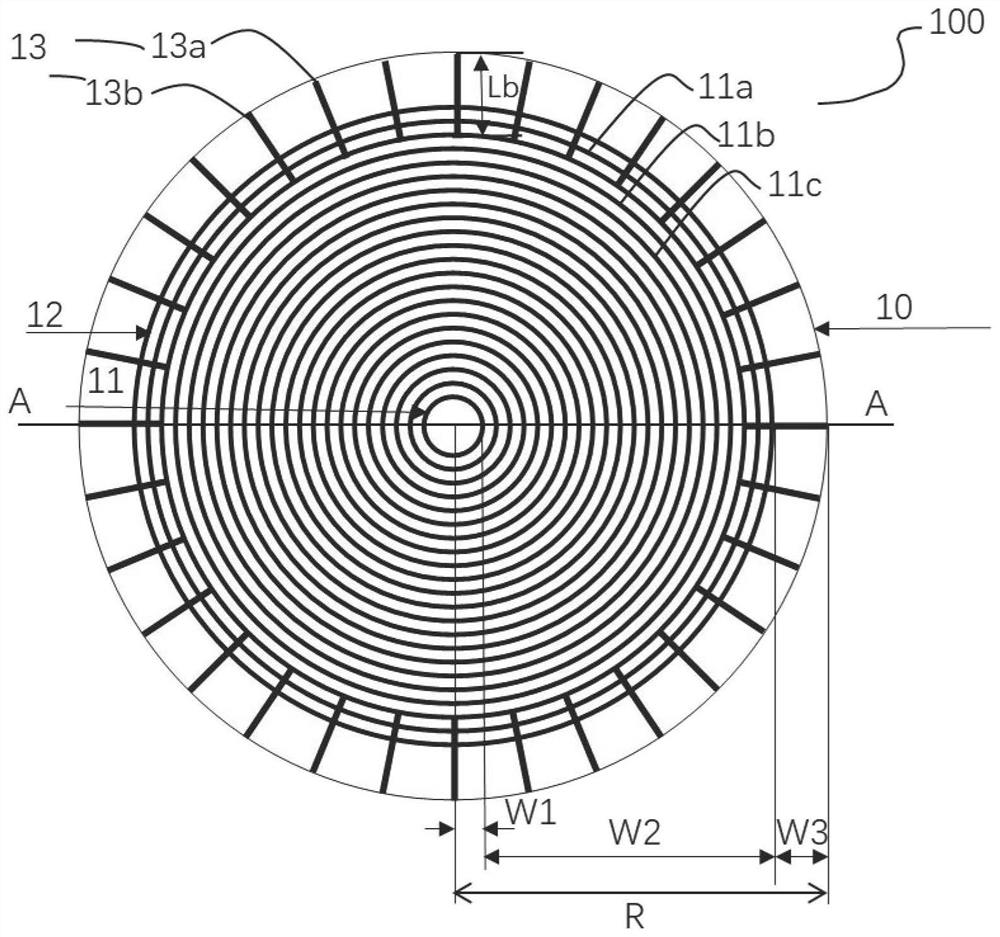
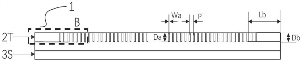
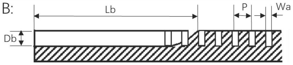
[0059] figure 1 is a plan view schematically showing a polishing pad according to a preferred embodiment of the present invention. refer to figure 1 , the polishing pad of the present invention is suitable for polishing or planarizing at least one of semiconductor, optical and magnetic substrates. The polishing pad includes an abrasive layer 100 . The grinding layer 100 includes at least two concentric circular grooves. The concentric circular grooves in the present invention refer to annular grooves with a common center but unequal radii. Define the innermost concentric circle groove as the first concentric circle 11, and the outermost concentric circle groove as the second concentric circle 12; the first concentric circle 11 and the second concentric circle 12 define multiple grinding areas, defined in the radial direction Above, the distance between the innermost side of the first concentric circle 11 and the center of the grinding layer is W1, the distance between the o...

Embodiment approach 2

[0097] As another preferred embodiment of the present invention, similar to Embodiment 1, in combination with the groove pattern of the present invention, the properties of the abrasive layer and buffer layer of the polishing pad are more preferably limited.

[0098] As a preferred embodiment of the present invention, the hardness range of the grinding layer is 50-67D, and the density range is 0.66-0.87g / cm 3 , the range of compression rate is 0.001-0.06. The hardness range of the buffer layer is 59-86A, and the density range is 0.25-0.4g / cm 3 , the range of compression ratio is 0.02-0.12.

[0099] More preferably, the hardness difference between the grinding layer and the buffer layer is in the range of 29-45.5D, and the density difference is in the range of 0.32-0.46g / cm 3 , the range of the absolute value of the compressibility difference is 0.025-0.089.

[0100] More preferably, the abrasive layer has a hardness in the range of 54-64D and a density in the range of 0.67-...

Embodiment approach 3

[0113] The third groove of the present invention is a linear groove. For example, the third grooves of Embodiments 1 to 2 are all linear. As another preferred embodiment of the present invention, the third groove of the third grinding area of ​​the polishing pad The grooves can also be curved. Combined with the groove pattern of the present invention, the properties of the abrasive layer and buffer layer of the polishing pad are more preferably defined, which are the same as those in the first and second embodiments, and will not be described again.

[0114] further reference Figure 5 , the polishing pad includes an abrasive layer 300, and the abrasive layer 300 is in direct contact with the material to be abrasive. The grinding layer 300 includes at least two concentric grooves, the first concentric circle and the second concentric circle define a plurality of grinding areas; the size and parameter range of the first grinding area and the second grinding area in the third e...


PUM


Abstract

The invention discloses a polishing pad, comprising a grinding layer, the grinding layer comprises at least two concentric circular grooves, the innermost concentric circular groove is defined as the first concentric circle, and the outermost concentric circular groove is defined as the second concentric circular groove. circle; the first concentric circle and the second concentric circle define a plurality of grinding areas, and the widths of the three grinding areas from the center of the circle to the edge of the grinding layer are W1, W2, and W3. The present invention uses different grinding areas and grooves of the polishing pad The relevant parameters of the groove and the physical parameters of the abrasive layer and the buffer layer are comprehensively designed, so that the polishing pad of the present invention has excellent comprehensive performance.

Description

technical field [0001] The invention relates to a polishing pad, in particular to a polishing pad with well-designed physical parameters of a grinding layer and a buffer layer and a surface groove structure, which is used for chemical mechanical polishing of abrasive materials. Background technique [0002] In the manufacturing and processing of integrated circuits, other electronic devices and optical materials, many materials are involved in polishing, thinning or planarization, among which chemical mechanical polishing is the most widely used. The principle of chemical mechanical polishing is that on a fixed polishing machine, the abrasive liquid is applied to the polishing pad. The polishing pad contacts the surface of the material to be ground, and a chemical reaction will occur. At the same time, the polishing pad and the material to be ground are processed on the machine The rotational movement, the mechanical action of shearing, the chemical action and the mechanical...

Claims


Application Information

Patent Timeline
Patent Type & Authority Patents(China)
IPC IPC(8): B24B37/26B24B37/22B24B37/24
CPCB24B37/26B24B37/22B24B37/24
Inventor 刘敏黄学良邱瑞英王腾杨佳佳张季平
Owner HUBEI DINGHUI MICROELECTRONICS MATERIALS CO LTD
Learn More