
Acid-based electrochemical flow battery

a flow battery and acid-based technology, applied in the field of electric energy accumulation system, to achieve the effect of high faradaic efficiency of the two reactions, high reversibility of the process, and virtually 100%

Active Publication Date: 2018-10-18
UNIV DE ALICANTE
View PDF4 Cites 0 Cited by
  • Summary
  • Abstract
  • Description
  • Claims
  • Application Information

AI Technical Summary

Benefits of technology

The present invention provides a system for reducing the inefficiencies associated with charging and discharging processes. The system has advantages such as high energy efficiency, simple design, low cost per unit of energy supplied, safer reagents, increased energy storage capacity, reduced inefficiencies of electrode processes, and eliminates the need for an electrochemical rebalancing system.

Problems solved by technology

In systems of this type, the electrode reactions of both redox pairs, which occur in the positive and negative electrodes, do not usually have the same Faradaic efficiency, so at the end of a certain number of charging / discharging cycles an imbalance in the charge contained in the solutions (state of charge), i.e., an imbalance in the concentrations of the active species, occurs, making it necessary to use a rebalancing system that offsets the lack of Faradaic synchronization of the processes (Z. Yang, J. Zhang, M. C. W. Kintner-Meyer, X. Lu, D. Choi, J. P. Lemmon, Electrochemical Energy Storage for Green Grid, Chemical Review, 111 (2011) 3577-3613; A. Z. Weber, M. M. Mench, J. P. Meyers, P. N. Ross, J. T. Gostick, Q. Liu, Redox flow batteries: a review, Journal of Applied Electrochemical, 41 (2011) 1137-1164).

Method used


Image

  • Acid-based electrochemical flow battery
  • Acid-based electrochemical flow battery
  • Acid-based electrochemical flow battery

Examples


example 1

[0039]In this example, a battery charging process is performed using 1 M NaOH and 1 M HCl as the posilyte and negalyte, respectively. Both solutions contain 2 M NaCl as the supporting electrolyte. The volume of the negalyte and posilyte is 50 ml. The electrode structure used is made up of a diffusion electrode formed by 20% wet-proofed Toray Paper TGPH-90 on which a microporous layer of a mixture of PTFE and Vulcan XC72 at a 60 / 40 weight ratio and a coating of 2.5 (mg Vulcan XC72) cm−2 is deposited. A catalytic layer is constructed on this layer using Pt / C at 30% by weight as an electrocatalyst and Nafion as a binder at a 60 / 40 ratio, the final catalytic coating being 1 (mg Pt) cm−2. This diffusion electrode is used in the oxidation reaction of hydrogen. Similarly, a platinized titanium electrode is used in the hydrogen formation reaction. Finally, the electrode geometric area of this system is 4 cm2.

[0040]The polarization curve (FIG. 6) of the system was first obtained, and then ch...

example 2

[0041]In this example, a battery discharging process is performed using 1 M NaOH and 1 M HCl as the negalyte and posilyte, respectively. Both solutions contain 2 M NaCl as the supporting electrolyte. The volume of the negalyte and posilyte is 50 mL. The electrodes described above were used as electrodes.

[0042]The polarization curve and power curve (FIG. 8) were first obtained, and then discharging was performed at a constant current density of 25 mA cm−2 for 7200 seconds. FIG. 9 shows the evolution of the potential difference over time.


PUM

PropertyMeasurementUnit
Faradaic efficiencyaaaaaaaaaa
current densityaaaaaaaaaa

Abstract

The present invention relates to a system and process for the accumulation of electrical energy, the system containing an electrochemical reactor comprising: an electrode compartment comprising molecular hydrogen, an electrode compartment comprising a liquid phase (a), an electrode compartment comprising a liquid phase (b), a catalytic surface comprising an electrocatalyst for the oxidation reaction of hydrogen, a catalytic surface comprising an electrocatalyst for the reduction reaction of water and an ion exchange membrane, wherein electrode compartment and electrode compartment are separated from one another by the catalytic surface, electrode compartment is in turn separated from electrode compartment by the ion exchange membrane and the free end of electrode compartment is in contact with the catalytic surface.

Description

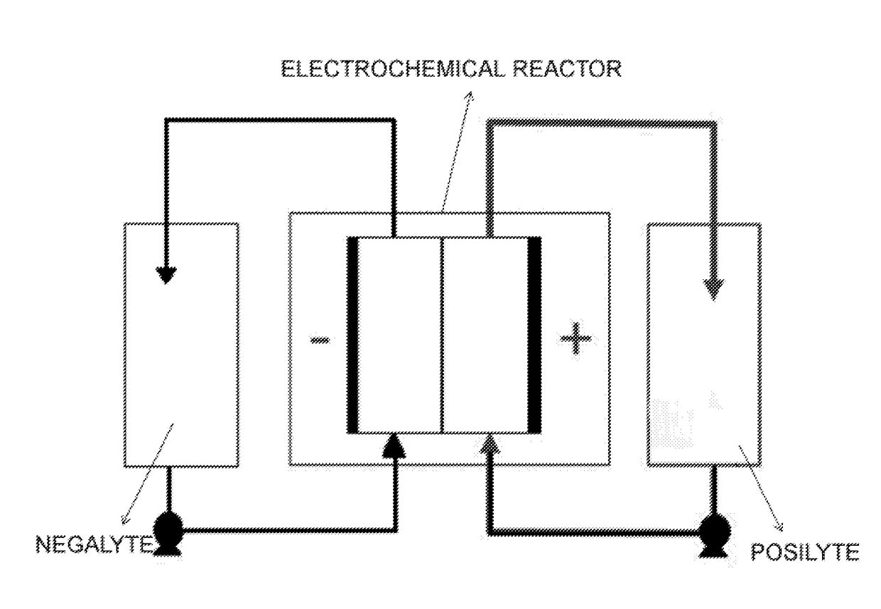
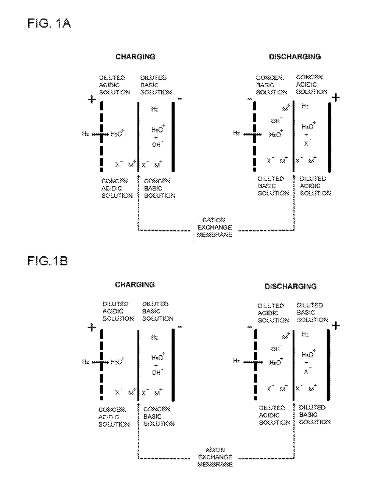
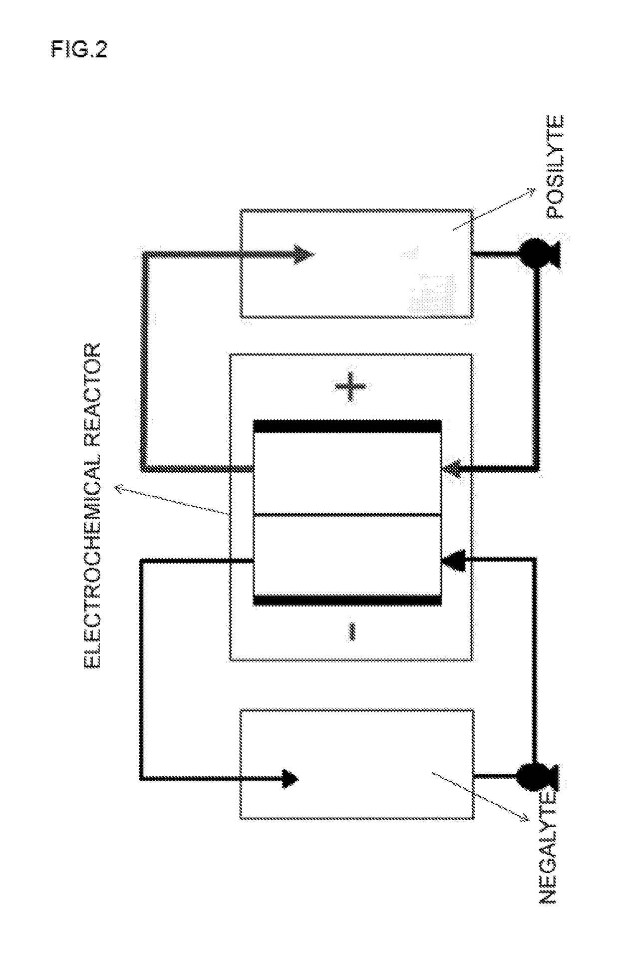
TECHNICAL FIELD[0001]The present invention relates to an electrical energy accumulation system which harnesses energy from the neutralization reaction of two solutions, one acidic and the other basic, converting it into electrical energy. In the electrical energy generation process (the system discharges and acts as a cell), the free energy released in the neutralization reaction of two highly concentrated solutions, one acidic and the other basic, separated by an ion exchange membrane is harnessed. During the discharging process, the concentration of the acidic and basic solutions decreases at the expense of providing electrical energy as a result of the neutralization process. In the charging process, electrical energy is injected to regenerate the initial state of the previous solutions. The redox processes of this electrochemical system are based on an oxidation reaction in which molecular hydrogen is oxidized to a proton and a reduction reaction in which water is reduced to mol...

Claims


Application Information

Patent Timeline
Patent Type & Authority Applications(United States)
IPC IPC(8): H01M8/18H01M8/04082
CPCH01M8/188H01M8/04201Y02E60/50Y02E60/10H01M8/04925H01M10/36H01M2300/0005H01M2300/0014H01M14/00H01M10/34
Inventor ALDAZ RIERA, ANTONIOMONTIEL LEGUEY, VICENTES EZ FERN NDEZ, ALFONSO
Owner UNIV DE ALICANTE
Learn More