
Encapsulated Cathode Active Material Particles, Lithium Secondary Batteries Containing Same, and Method of Manufacturing

a cathode active material and active material technology, applied in the field of rechargeable lithium batteries, can solve the problems of inability to deliver high pulse power, limiting the choice of available cathode materials, and the specific capacity of commonly used cathode active materials

Active Publication Date: 2018-10-11
GLOBAL GRAPHENE GRP INC
View PDF7 Cites 16 Cited by
  • Summary
  • Abstract
  • Description
  • Claims
  • Application Information

AI Technical Summary

Benefits of technology

This patent discusses a new type of material used in lithium battery cathodes, which helps to overcome the problem of rapid capacity decay. The material is made up of a high-elasticity polymer that encapsulates the cathode active material particles. This polymer prevents direct contact between the electrolyte and the cathode material, which could cause damage and reduce battery performance. It also prevents the dissolution of active material in the electrolyte, which can lead to continued loss of performance and capacity. Overall, this new material helps to create safer and more reliable lithium batteries.

Problems solved by technology

However, the use of graphite-based anodes in Li-ion batteries has several significant drawbacks: low specific capacity (theoretical capacity of 372 mAh / g as opposed to 3,860 mAh / g for Li metal), long Li intercalation time (e.g. low solid-state diffusion coefficients of Li in and out of graphite and inorganic oxide particles) requiring long recharge times (e.g. 7 hours for electric vehicle batteries), inability to deliver high pulse power (power density <0.5 kW / kg), and necessity to use pre-lithiated cathodes (e.g. lithium cobalt oxide, as opposed to cobalt oxide), thereby limiting the choice of available cathode materials.
Further, these commonly used cathode active materials have a relatively low specific capacity (typically <220 mAh / g).
To sum it up, battery scientists have been frustrated with the low energy density, inadequate cycle life, and flammability of lithium-ion cells for over three decades!
However, current and emerging cathode active materials for lithium secondary batteries still suffer from the following serious drawbacks:(1) The most commonly used cathode active materials (e.g. lithium transition metal oxides) contain a transition metal (e.g. Fe, Mn, Co, Ni, etc.) that is a powerful catalyst that can promote undesirable chemical reactions inside a battery (e.g. decomposition of electrolyte).
These cathode active materials also contain a high oxygen content that could assist in the progression of thermal runaway and provide oxygen for electrolyte oxidation, increasing the danger of explosion or fire hazard.
This is a serious problem that has hampered the widespread implementation of electric vehicles.(2) Most of promising organic or polymeric cathode active materials are either soluble in the commonly used electrolytes or are reactive with these electrolytes.
Dissolution of active material in the electrolyte results in a continuing loss of the active material.
Undesirable reactions between the active material and the electrolyte lead to graduate depletion of the electrolyte and the active material in the battery cell.
All these phenomena lead to capacity loss of the battery and shortened cycle life.(3) The practical capacity achievable with current cathode materials (e.g. lithium iron phosphate and lithium transition metal oxides) has been limited to the range of 150-250 mAh / g and, in most cases, less than 200 mAh / g.
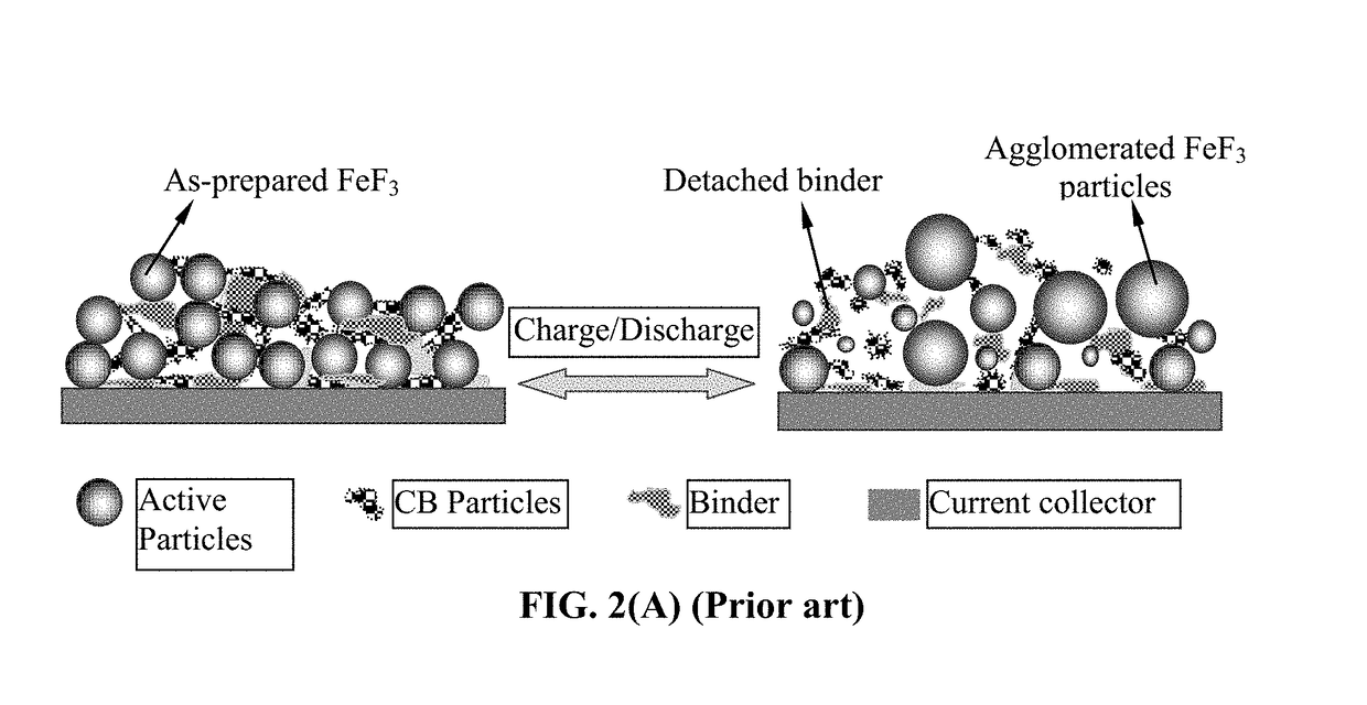
Additionally, emerging high-capacity cathode active materials (e.g. FeF3) still cannot deliver a long battery cycle life.
These repeated volume changes lead to structural instability of the cathode, breakage of the normally weak bond between the binder resin and the active material, fragmentation of active material particles, delamination between the cathode active material layer and the current collector, and interruption of electron-conducting pathways.

Method used


Image

  • Encapsulated Cathode Active Material Particles, Lithium Secondary Batteries Containing Same, and Method of Manufacturing
  • Encapsulated Cathode Active Material Particles, Lithium Secondary Batteries Containing Same, and Method of Manufacturing
  • Encapsulated Cathode Active Material Particles, Lithium Secondary Batteries Containing Same, and Method of Manufacturing

Examples


example 1

Cathode Active Material Layers Containing High-Elasticity UHMW Polymer-Encapsulated V2O5 Particles

[0110]Cathode active material layers were prepared from V2O5 particles and graphene-embraced V2O5 particles, respectively. V2O5 particles were commercially available. Graphene-embraced V2O5 particles were prepared in-house. In a typical experiment, vanadium pentoxide gels were obtained by mixing V2O5 in a LiCl aqueous solution. The Li+ exchanged gels obtained by interaction with LiCl solution (the Li:V molar ratio was kept as 1:1) was mixed with a GO suspension and then placed in a Teflon-lined stainless steel 35 ml autoclave, sealed, and heated up to 180° C. for 12 h. After such a hydrothermal treatment, the green solids were collected, thoroughly washed, ultrasonicated for 2 minutes, and dried at 70° C. for 12 h followed by mixing with another 0.1% GO in water, ultrasonicating to break down nano-belt sizes, and then spray-drying at 200° C. to obtain graphene-embraced V2O5 composite pa...

example 2

High-Elasticity Polymer Binder-Bonded Lithium Iron Phosphate (LFP) Particles

[0120]The high-elasticity polymer for encapsulation of LFP particles was based on ultra-high molecular weight polyacrylonitrile (UHMW PAN). UHMW PAN (0.3 g) was dissolved in 5 ml of dimethylformamide (DMF) to form a solution. The LFP particles were then dispersed in the solution to form a slurry. The slurries were then separately subjected to a micro-encapsulation procedure to produce anode active material particles having entire exterior surfaces being coated with an embracing layer of the polymers.

[0121]Polymer films for elasticity testing were cast from the prepared solutions on a glass support, followed by solvent evaporation at 70° C. under a fume hood. To remove the traces of DMF, the films were thoroughly dried in a vacuum (<1 Torr) at 70° C. for 48 h. The polymer films were soaked in propylene carbonate (PC) to form PC-plasticized UHMW PAN films. Tensile testing was also conducted on these films and ...

example 3

Metal Fluoride Nano Particles Encapsulated by an UHMW PPO

[0123]For encapsulation of FeF3 nano particles, an UHMW PPO polymer was implemented as an embracing polymer shell by using a procedure similar to that described in Example 1. Commercially available powders of CoF3, MnF3, FeF3, VF3, VOF3, TiF3, and BiF3 were subjected to high-intensity ball-milling to reduce the particle size down to approximately 0.5-2.3 μm. Each type of these metal fluoride particles, along with graphene sheets (as a conductive additive), was then added into a UHMW PPO-solvent liquid suspension to form a multiple-component slurry. The slurry was then spray-dried to form isolated polymer embraced particles.

[0124]Shown in FIG. 5 are the discharge capacity curves of two coin cells having two different types of cathode active materials: (1) high-elasticity UHMW PPO polymer-encapsulated metal fluoride particles and (2) non-encapsulated metal fluorides. These results have clearly demonstrated that the high-elastici...


PUM

PropertyMeasurementUnit
thicknessaaaaaaaaaa
lithium ion conductivityaaaaaaaaaa
tensile strainaaaaaaaaaa

Abstract

Provided is particulate of a cathode active material for a lithium battery, comprising one or a plurality of cathode active material particles being embraced or encapsulated by a thin layer of a high-elasticity polymer having a recoverable tensile strain no less than 5%, a lithium ion conductivity no less than 10−6 S / cm at room temperature, and a thickness from 0.5 nm to 10 μm, wherein the polymer contains an ultrahigh molecular weight (UHMW) polymer having a molecular weight from 0.5×10⁶ to 9×10⁶ grams / mole. The UHMW polymer is preferably selected from polyacrylonitrile, polyethylene oxide, polypropylene oxide, polyethylene glycol, polyvinyl alcohol, polyacrylamide, poly(methyl methacrylate), poly(methyl ether acrylate), a copolymer thereof, a sulfonated derivative thereof, a chemical derivative thereof, or a combination thereof.

Description

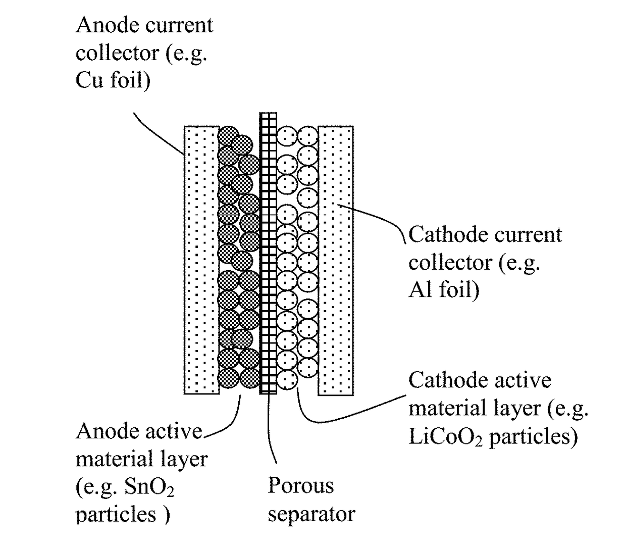
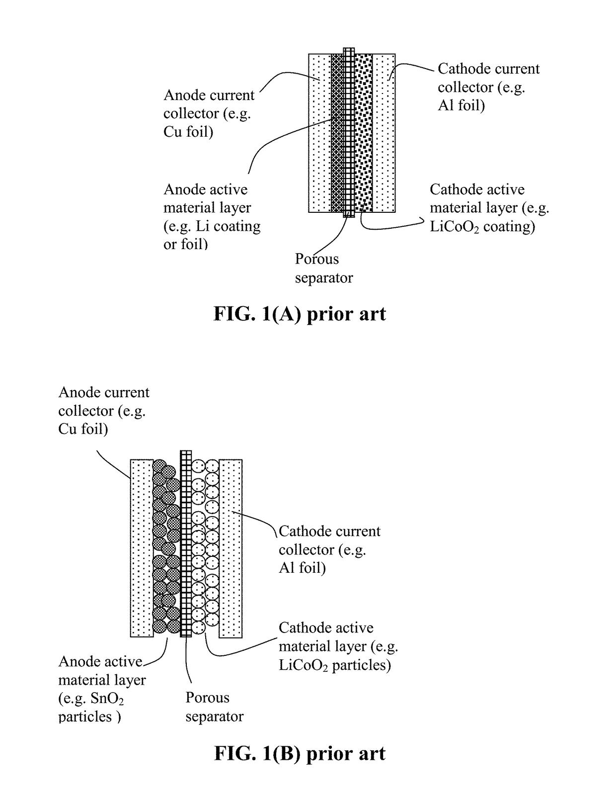
FIELD OF THE INVENTION[0001]The present invention relates generally to the field of rechargeable lithium battery and, more particularly, to the lithium battery cathode active material, cathode layer, and battery cell, and a method of manufacturing same.BACKGROUND OF THE INVENTION[0002]A unit cell or building block of a lithium-ion battery is typically composed of an anode current collector, an anode or negative electrode layer (containing an anode active material responsible for storing lithium therein, a conductive additive, and a resin binder), an electrolyte and porous separator, a cathode or positive electrode layer (containing a cathode active material responsible for storing lithium therein, a conductive additive, and a resin binder), and a separate cathode current collector. The electrolyte is in ionic contact with both the anode active material and the cathode active material. A porous separator is not required if the electrolyte is a solid-state electrolyte.[0003]The binder...

Claims


Application Information

Patent Timeline
Patent Type & Authority Applications(United States)
IPC IPC(8): H01M4/36H01M10/0525H01M4/62H01M4/131H01M4/1391H01M4/48C08K3/26C08K5/10C08K3/16C08K3/22C08K5/098C08L71/02C08L33/20C08K9/08C08K9/10C08K3/04C08K3/10C08K3/34C08K3/30
CPCH01M4/366C08K2201/001H01M4/625H01M4/623H01M4/131H01M4/1391H01M4/48C08K3/26C08K5/10C08K3/16C08K3/22C08K5/098C08L71/02C08L33/20C08K9/08C08K9/10C08K3/04C08K3/10C08K3/041C08K3/34C08K3/30H01M2220/20C08K2003/262C08K2003/2203C08L2205/025C08L2203/20C08K2003/3009H01M10/0525H01M4/5815H01M4/5825H01M4/602H01M4/62H01M4/624H01M2300/0082H01M2300/0091C08K5/04C08K3/38Y02E60/10C08L33/12C08L29/04C08L33/02H01M10/052C08K3/08C08L5/10C08K5/36C08L79/02C08L65/00
Inventor ZHAMU, ARUNAJANG, BOR Z.
Owner GLOBAL GRAPHENE GRP INC
Learn More