Barrier layer delaying oxygen depletion in sealed gas-filled LED lamps

a barrier layer and led lamp technology, applied in the field of lighting units, can solve the problems of thermal oxidation of hermetically sealed led bulbs filled with helium (and oxygen) for cooling, negative impact on the thermal resistance (rth) of the gas-filled lamp, etc., to achieve the effect of reducing the level of o2 required to meet lifetime requirements, reducing the content of o2, and reducing the thermal oxidation of epoxy comprising composite materials

Inactive Publication Date: 2018-09-06
SIGNIFY HLDG BV
View PDF4 Cites 1 Cited by
  • Summary
  • Abstract
  • Description
  • Claims
  • Application Information

AI Technical Summary

Benefits of technology

The patent proposes a way to increase the lifespan of a lighting unit by using a copper layer on the non-functional side of the circuit board. This barrier layer helps to reduce the oxidation of the epoxy material used in the circuit board, which prevents premature failure and allows for a lower oxygen content. This results in better thermal resistance and higher efficiency of the lighting unit, without the need for additional power and oxygen. The support layer of the lighting unit consists of layers with different electrical conductivity, including copper, epoxy-based material, and an oxygen barrier layer. This design also helps to prevent the migration of oxygen from the envelope to the circuit board, which can cause premature aging of the plastic material used for optical properties. Overall, the invention offers an improved lifetime and efficiency for lighting units while maintaining their power output.

Problems solved by technology

Hermetically sealed LED bulbs which are filled with helium (and oxygen) for cooling appear to suffer from thermal oxidation when standard single-sided copper (SSC) “copper clad laminates” (CCL) are used as printed circuit board (PCB) material.
However, the supply of additional O2 negatively impacts the thermal resistance (Rth) of the gas-filled lamp.

Method used


Image

  • Barrier layer delaying oxygen depletion in sealed gas-filled LED lamps
  • Barrier layer delaying oxygen depletion in sealed gas-filled LED lamps
  • Barrier layer delaying oxygen depletion in sealed gas-filled LED lamps

Examples


Embodiment Construction

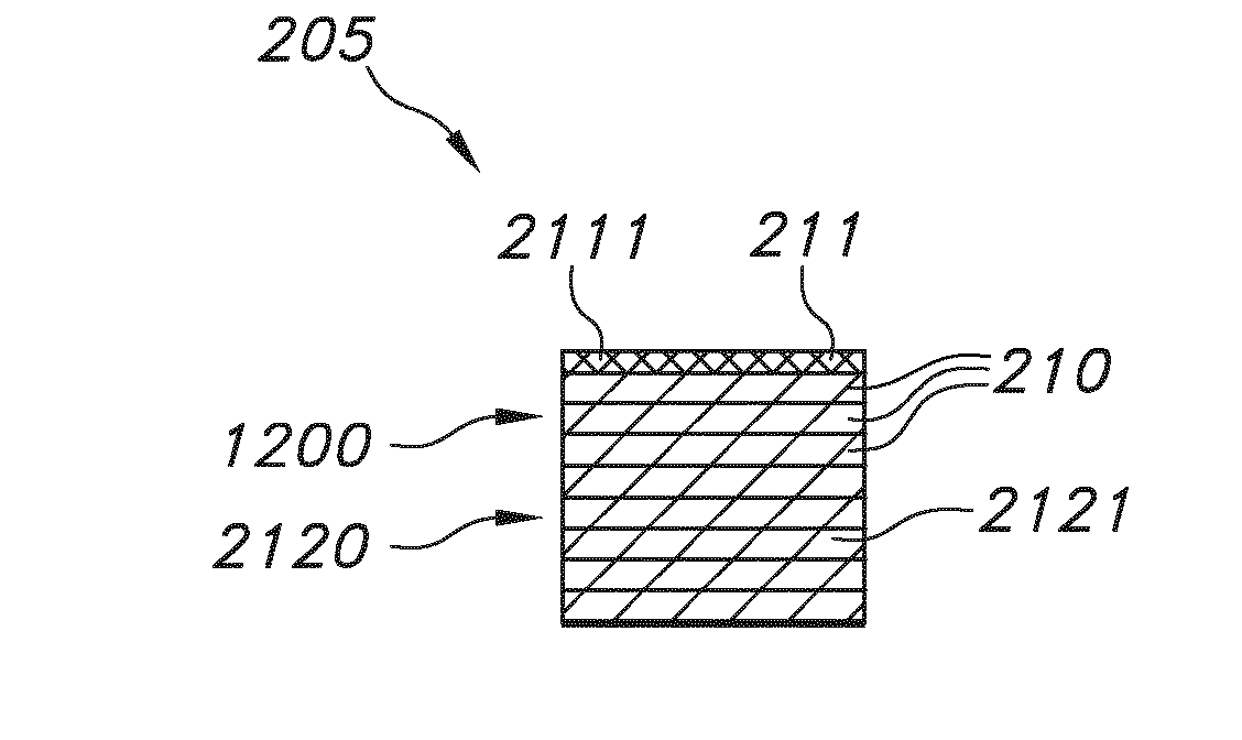
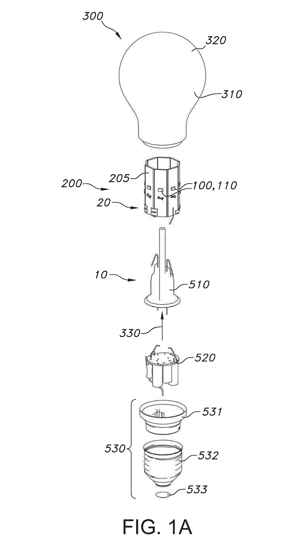
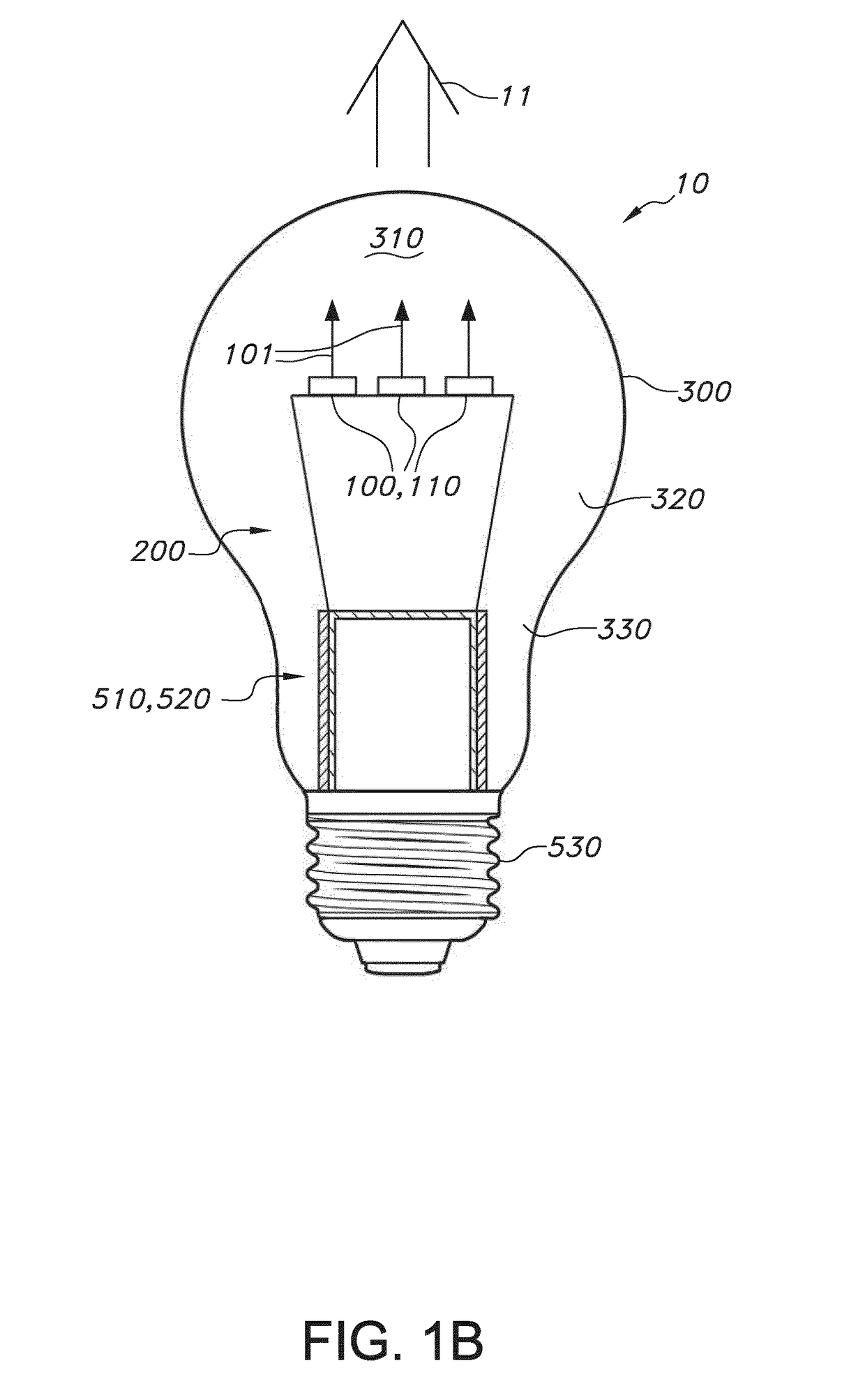
[0062]FIGS. 1a-1b schematically depict designs of a low cost LED bulb / lighting unit using a conventional glass bulb that can be filled with He and O2.

[0063]FIG. 1a schematically depicts an embodiment how the lighting unit may be assembled, hereby assuming that the assembly, indicated with reference 20, is available. FIG. 1a schematically depicts the assembly of the lighting unit 10 comprising a lighting device 100, a support 200, and an envelope 300. The lighting device 100 is configured to provide lighting device light (not depicted). The lighting device 100 comprises a light source 110. The support 200 is configured to support the light source 110. The support 200 with functionally coupled light source 110 is herein also indicated as assembly 20. The envelope 300 provides a sealed space 310 enclosing the light source 110 and at least part of the support 200. The envelope 300 comprises an envelope part 320 transmissive for the lighting device light 101. For instance, the envelope 3...


PUM


Abstract

The invention provides a lighting unit (10) comprising (a) a lighting device (100), (b) a support (200), and (c) an envelope (300), wherein: —the lighting device (100) is configured to provide lighting device light (101); wherein the lighting device (100) comprises a light source (110); —the support (200) is configured to support the light source (110); wherein the 5 support (200) comprises a laminate of layers, wherein the laminate of layers comprises an electrically conductive first layer, an electrically non-conducive second layer), and a third layer, wherein the first layer comprises copper, wherein the second layer comprises an epoxy-based material, and wherein the third layer comprises an oxygen barrier material; —the envelope (300) is configured to provide a sealed space (310) enclosing the 10 light source (110) and at least part of the support (200); wherein the envelope (300) comprises an envelope part (320) transmissive for the lighting device light (101), and wherein the sealed space (310) comprise a filling gas (330) comprising a thermally conductive gas, wherein the filling gas (330) at least comprises oxygen (O2).

Description

FIELD OF THE INVENTION[0001]The invention relates to a lighting unit. The invention also relates to an assembly of a light source and support for use in such lighting unit. The invention also relates to a method for producing such assembly. The invention further relates to a method for producing the lighting unit.BACKGROUND OF THE INVENTION[0002]Lighting bulbs with LEDs and a filling gas are known in the art. WO2013154932, for instance, describes that in a sealed environment operating an LED in an oxygen depleted environment may cause degradation of the LED. One result of such degradation is the browning of the silicone that may be used as an encapsulant for the LED chip. According to WO2013154932, it is believed that the browning of the silicone may be caused by a combination of the environment in which the LED is operated (oxygen depleted), contaminants such as organics in the LED assembly or other components in the enclosure, the flux density of the optical energy from the LEDs a...

Claims


Application Information

Patent Timeline
Patent Type & Authority Applications(United States)
IPC IPC(8): H05K1/18F21K9/232H05K1/03F21K9/64H05K1/09F21V29/50
CPCF21K9/64H05K1/09F21V29/50H05K2201/10106F21Y2115/10H05K1/181F21K9/232H05K1/032F21V29/85Y02P70/50
Inventor VELDMAN, DIRKVAN KOOTEN, WIJNAND EVERT JACOBUSBEIJER, JOHANNES GERRIT JANCAERS, JOHAN FRANS JUSTIN MARIA
Owner SIGNIFY HLDG BV
Why Eureka
Try Eureka