
Features for Implants with a Reduced Volumetric Density of Surface Roughness

Pending Publication Date: 2018-08-30
NANOHIVE MEDICAL LLC
View PDF2 Cites 13 Cited by
  • Summary
  • Abstract
  • Description
  • Claims
  • Application Information

AI Technical Summary

Benefits of technology

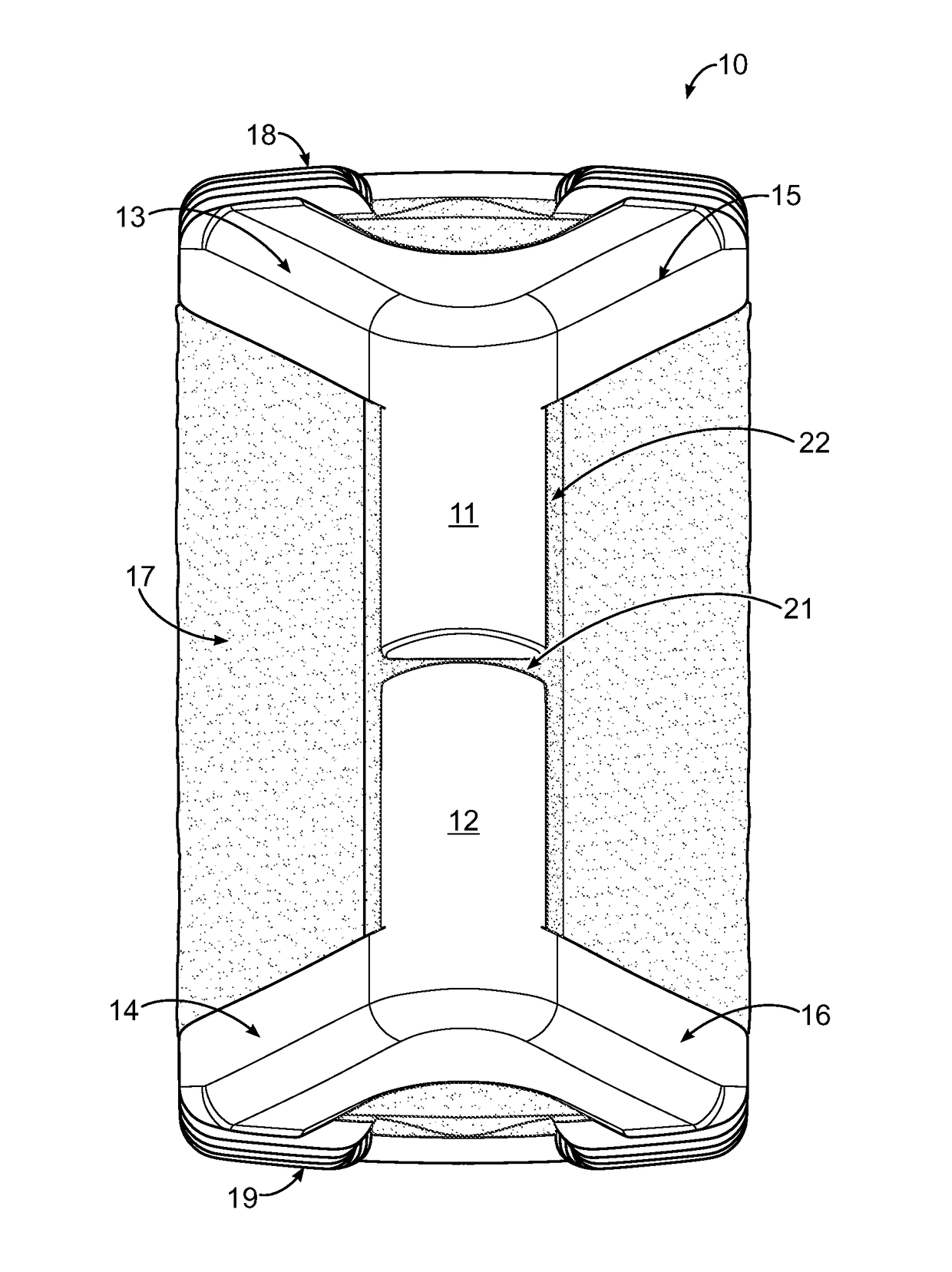
The invention provides a method for designing and manufacturing implants using an additive process that avoids damage when removing the implant from a build surface of an additive process machine. The method involves designing an implant with increased volumetric density in contact with the build surface and reducing the contact area between the device and the build surface to make detachment easier after the additive process is complete. The implant features protrusions mounted on the forward edge of the implant that can ease the distraction of tissue during implantation and reduce the occurrence of damage during a manufacturing process. The protrusions have gaps in a non-axial direction with respect to the implant to allow axial compression with respect to the protrusions and a circumferential gap between them and a body of a device to reduce any impact on the device's elastic modulus. The technical effect of the invention is a method for making implants with reduced damage and improved outcomes during manufacturing processes. Implant features like protrusions can also help reduce the likelihood of complications and damage during implantation.

Problems solved by technology

Despite the advantages of additive processes, as the surface porosity of an object increases or the volumetric density of the object's surface decreases, it becomes increasing difficult to break the bond between the platform and the first layer without damage after the manufacturing process is complete.
When an additive process is used to manufacture an implant with a highly porous surface or a low volumetric density structure, the surface area of the implant or outer layers of the structure attached to the platform are likely to be damaged during removal.

Method used


Image

  • Features for Implants with a Reduced Volumetric Density of Surface Roughness
  • Features for Implants with a Reduced Volumetric Density of Surface Roughness
  • Features for Implants with a Reduced Volumetric Density of Surface Roughness

Examples


Embodiment Construction

[0044]In many situations, it is desirable to use an implant that is capable of bone attachment or osteointegration over time. It is also desirable in many situations to use an implant that is capable of attachment or integration with living tissue. Examples of implants where attachment to bone or osteointegration is beneficial include, but are not limited to, cervical, lumbar, and thoracic interbody fusion implants, vertebral body replacements, osteotomy wedges, dental implants, bone stems, acetabular cups, cranio-facial plating, bone replacement and fracture plating. In many applications, it is also desirable to stress new bone growth to increase its strength. According to Wolff's law, bone will adapt to stresses placed on it so that bone under stress will grow stronger and bone that isn't stressed will become weaker.

[0045]In some aspects, the systems and methods described herein can be directed toward implants that are configured for osteointegration and stimulating adequately str...


PUM

PropertyMeasurementUnit
Fractionaaaaaaaaaa
Fractionaaaaaaaaaa
Fractionaaaaaaaaaa

Abstract

The invention disclosed herein includes implant features that can be used, in some embodiments, on devices with a volumetric density of less than about 100 percent and devices with a surface roughness of some value. The implant features include one or more protrusions mounted on the forward edge of an implant that can ease the distraction of tissue during implantation and reduce the occurrence of damage during a manufacturing process. In some embodiments, the protrusions have gaps in a non-axial direction with respect to the implant to allow axial compression with respect to the protrusions. In some embodiments, the protrusions have a circumferential gap between them and a body of a device to reduce any impact on the device's elastic modulus.

Description

CROSS REFERENCE TO RELATED APPLICATIONS[0001]This application claims the benefit of U.S. Provisional Patent Application No. 62 / 463,089 filed Feb. 24, 2017, U.S. Provisional Patent Application No. 62 / 480,383 filed Apr. 1, 2017, U.S. Provisional Patent Application No. 62 / 480,391 filed Apr. 1, 2017, and U.S. Provisional Patent Application No. 62 / 619,260 filed Jan. 19, 2018, which are hereby incorporated by reference in their entirety.FIELD OF THE INVENTION[0002]The present invention relates to implant features and the design and manufacture of implants with a reduced volumetric density and, in particular, to implant features and a method of using an additive process to manufacture implants with a lattice structure.BACKGROUND OF THE INVENTION[0003]Medical implants with porous or open cell structures are useful for providing a scaffold for bone or tissue growth. Existing methods of manufacturing implants with porous or open cell structures include the use of additive processes, such as d...

Claims


Application Information

Patent Timeline
IPC IPC(8): A61F2/28A61F2/00B22F3/105
CPCA61F2/28A61F2/0077B22F3/1055A61L2400/18A61L27/54A61F2002/0081A61L27/32A61L27/06A61F2/4455A61F2002/30084A61F2002/30006A61F2002/3092A61F2002/30914B22F2005/005A61F2/447A61F2002/30014A61F2002/30016A61F2002/30143A61F2002/30146A61F2002/30153A61F2002/30158A61F2002/3028A61F2002/30593A61F2002/30594A61F2002/30904A61F2002/30971A61F2002/30985A61F2002/4629B33Y50/00B33Y80/00A61F2002/30141A61F2002/30148A61F2002/30149A61F2002/30151A61F2002/30154A61F2002/30156A61F2002/30273A61F2002/3093A61F2002/30968A61F2002/30028B22F10/62B22F10/66B22F10/25B22F10/28B22F10/47Y02P10/25B33Y10/00A61F2/30767A61F2/30942A61F2/4465A61F2002/30331A61F2002/3097B23K15/0086
Inventor JONES, CHRISTOPHER L.HELMAR, IANDIEHL, LUCASTINLEY, JASONCHAPPUIS, KEVIN D.SULLIVAN, JOHN F.
Owner NANOHIVE MEDICAL LLC
Learn More