
Pellicle frame, pellicle containing same, method for producing pellicle frame, and method for producing pellicle

Active Publication Date: 2018-08-23
MITSUI CHEM INC
View PDF0 Cites 4 Cited by
  • Summary
  • Abstract
  • Description
  • Claims
  • Application Information

AI Technical Summary

Benefits of technology

The present invention provides a pellicle frame that is less likely to outgas and generate foreign particles. This results in highly precise patterning due to a mask and pellicle membrane that are free from contamination. In simple terms, this invention provides a cleaner and more reliable way to produce highly precise patterns.

Problems solved by technology

This causes reduction of patterning precision to impair the quality and / or appearance of the obtained device.
In such a pellicle frame, the residual ions are outgassed to fog up the pellicle membrane, or react with other ions to cause foreign particles, and thus patterning precision becomes more likely to decrease.
To address the above problems, sealing the anodic oxide film is considered, however, the effect thereof is not satisfactory.

Method used


Image

  • Pellicle frame, pellicle containing same, method for producing pellicle frame, and method for producing pellicle
  • Pellicle frame, pellicle containing same, method for producing pellicle frame, and method for producing pellicle
  • Pellicle frame, pellicle containing same, method for producing pellicle frame, and method for producing pellicle

Examples


example 1

[0111]An aluminum frame of JIS A7075-T6 (size: 149 mm×122 mm×5.8 mm height, supporting frame thickness: 2 mm) was provided. The frame was annealed at the temperature of 250° C. for 20 minutes in the atmosphere. The frame surface was then subjected to shot-blasting with stainless steel having an average diameter of about 100 μm. The frame was anodized using an electrolytic bath with 15 mass % of sulfuric acid at an electrolytic voltage of 20V and electric quantity of 10 C / cm2. Subsequently, electrolytic deposition was performed at 30° C. by constant voltage electrolysis at an AC voltage of 15V for 6 minutes, using an electrolytic deposition bath with 160 g / L of nickel sulfate hexahydrate, 40 g / L of boric acid, 3 g / L of tartaric acid and 1 g / L of magnesium oxide dissolved therein, thereby obtaining a colored frame.

[0112]The obtained frame was washed with pure water, and subjected to electrodeposition coating in a bath containing a cationic polyimide-electrodeposition coating material ...

example 2

[0113]Pellicle frame 2 was produced in substantially the same manner as in Example 1 except that the anodizing treatment and electrodeposition coating were performed under the following conditions.

[0114](Anodizing Treatment)

[0115]Anodizing treatment was performed at 5° C., an electrolytic voltage of 30V and electric quantity of 10 C / cm2, using an alkaline aqueous solution having 53 g / 1l of sodium tartrate dihydrate and 4 g / L of sodium hydroxide dissolved therein as an electrolyte.

[0116](Electrodeposition Coating)

[0117]The frame after subjected to the electrolytic deposition was washed with pure water, and placed in a bath containing a cationic polyimide-electrodeposition coating material (ELECOAT PI manufactured by Shimizu co., Ltd). Electrodeposition coating was then performed at 25° C. and a voltage of 100V for one minute, using a carbon plate as the positive electrode and the frame as the negative electrode. The frame was washed with water, dried and baked in the same manner as i...

example 3

[0118]A frame-shaped aluminum alloy A7075 frame material (outer size: 148.95 mm×114.95 mm×2.50 mm thickness) was subjected to anodizing treatment under the following conditions. Subsequently, electrodeposition coating in the same manner as in Example 2 was performed to obtain pellicle frame 3 having an electrodeposited coating (polyimide resin-containing film) with a thickness of 5 to 20 μm formed thereon.

[0119](Anodizing Treatment)

[0120]Anodizing treatment was performed using an alkaline aqueous solution having an inorganic acid hydrate dissolved therein as an electrolyte under the conditions such that the pH of the solution was 12 to 14, a bath temperature was 0 to 20° C., a voltage was 0.5V or more to less than 20V and a treating time was 2 to 120 minutes.


PUM

PropertyMeasurementUnit
Thicknessaaaaaaaaaa
Fractionaaaaaaaaaa
Fractionaaaaaaaaaa

Abstract

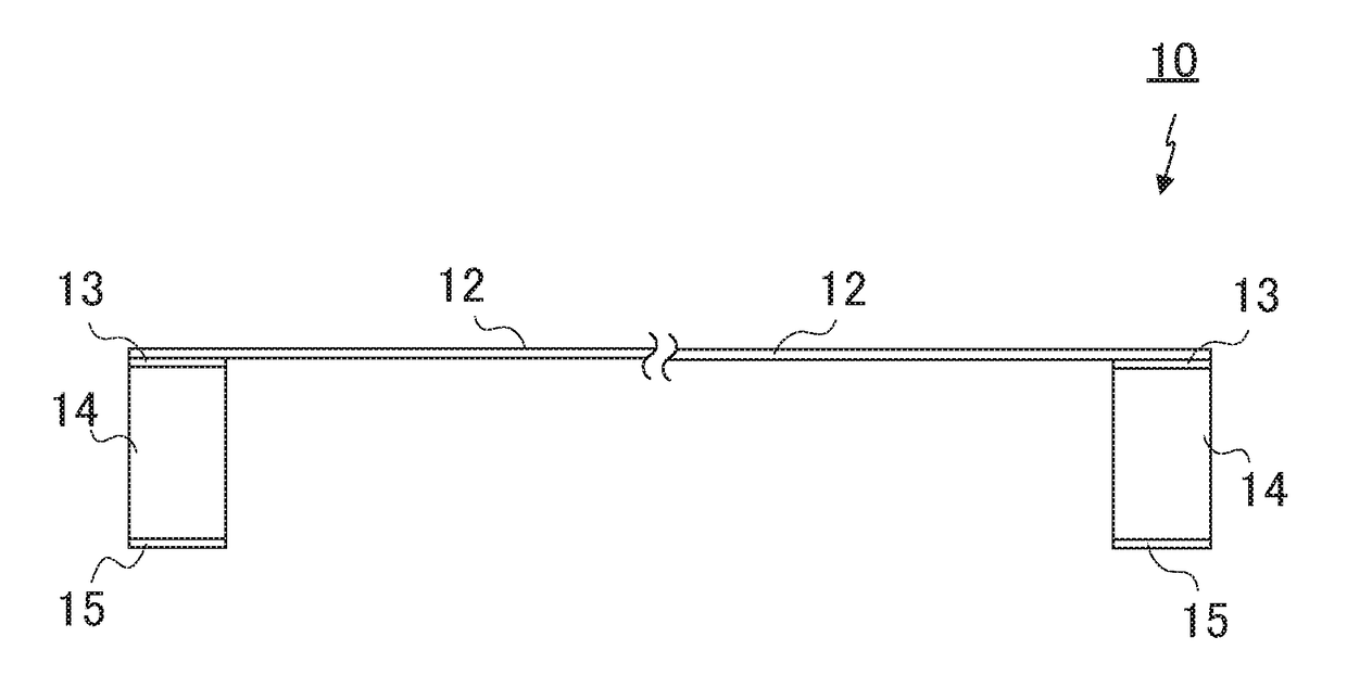
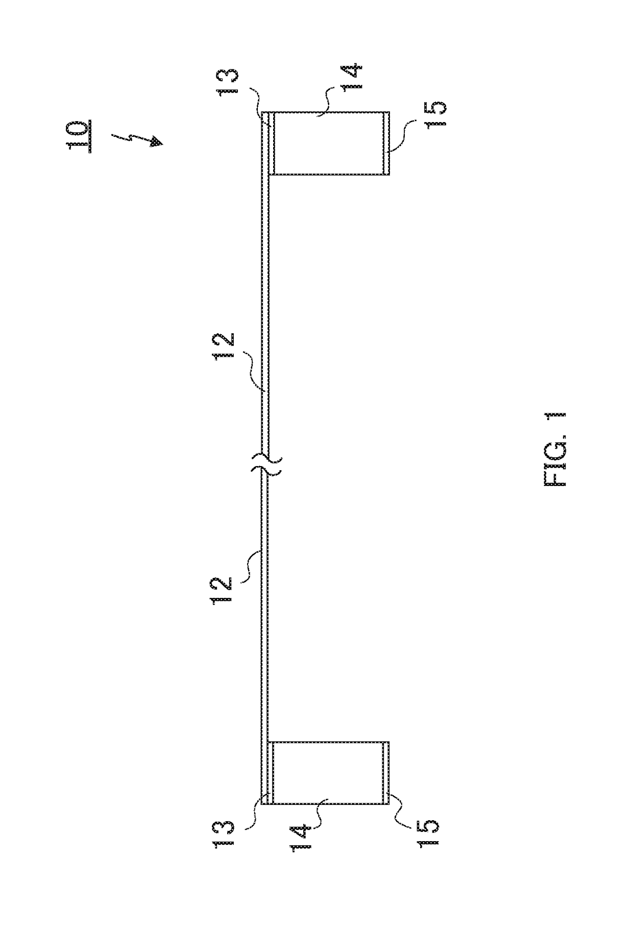
The purpose of the present invention is to provide: a pellicle frame which is not susceptible to deterioration even if irradiated with short-wavelength light such as excimer light, and which is not susceptible to generation of an outgas or foreign substance; and a pellicle which uses this pellicle frame. In order to achieve the above-described purpose, this pellicle frame for supporting the outer periphery of a pellicle film is configured to comprise a frame and a film that is formed on the surface of the frame and contains a polyimide resin.

Description

TECHNICAL FIELD[0001]The present invention relates to a pellicle frame, a pellicle including the same, a method for producing the pellicle frame, and a method for producing the pellicle.BACKGROUND ART[0002]During the process for producing semiconductor devices, such as an LSI and a VLSI, a liquid crystal display panel, and the like, various patterns are formed by irradiation with light via a mask (original plate for exposure). When a foreign particle is attached to the mask during the process, the foreign particle absorbs and / or refracts light. This causes reduction of patterning precision to impair the quality and / or appearance of the obtained device. Typically, a pellicle is attached on the surface of a mask to suppress attachment of foreign particles to the mask.[0003]A pellicle is generally composed of a pellicle membrane capable of transmitting light for patterning, and a pellicle frame supporting the periphery of the pellicle membrane. The pellicle frame is composed of a metal...

Claims


Application Information

Patent Timeline
IPC IPC(8): G03F1/64B32B15/08
CPCG03F1/64B32B15/08B32B2379/08B32B2311/24C25D11/22G03F1/62G03F1/66
Inventor KOHMURA, KAZUOKOZEKI, TAKASHITANEICHI, DAIKIMAEKAWA, SHINTAROONO, YOSUKEBIYAJIMA, TSUNEAKI
Owner MITSUI CHEM INC
Learn More