
Actuating device for a motor vehicle brake system

a technology for brake systems and actuators, applied in brake systems, brake action initiation, transportation and packaging, etc., can solve problems such as inability to lock, reduce the installation length, and reduce the effect of installation length

Active Publication Date: 2018-08-02
IPGATE
View PDF6 Cites 0 Cited by
  • Summary
  • Abstract
  • Description
  • Claims
  • Application Information

AI Technical Summary

Benefits of technology

The solution achieves a shorter installation length, higher reliability, and reduced pedal travel losses, ensuring safer and more reliable braking performance even in the event of brake booster failure, while allowing for diagnostic validation of safety components.

Problems solved by technology

If the pressure supply fails during braking, however, system weakness is unavoidable and can lead to accidents.
Here the solenoid valve is, if currentless, normally open, meaning that if the power fails a considerable pedal loss occurs through the take-up of the volume of the piston in the travel simulator.
Here also a pedal travel loss results.
If the brake booster fails this locking does not work, and the brake pedal operates with less pedal loss on the tandem main cylinder for pressure generation.
There is also a disadvantage here that in the event of failure of the brake booster during braking this pedal loss reoccurs.
This solution also involves a long installation length, which from the crash point of view is a disadvantage since, for example, the engine presses on the tandem main cylinder with the brake booster thereby pushing the pedal back leading to considerable foot injuries.
This solution is complicated and requires a long installation length.
A complaint about travel simulator systems is that when braking with the vehicle at a standstill the hard stop when the travel simulator actuates is perceptible and irritates the driver.
During braking to a standstill this is not the case, since the foot force immediately follows the vehicle deceleration and the hard stop is only reached at full braking.
Systems with travel simulator are extremely safety-critical, since in the event of failure of the brake booster the fallback solution must operate reliably.
In systems in which the push-rod piston during operation requires the volume in the travel simulator piston, the problem arises that in the event of failure of the brake booster this volume is missing from the brake circuit with subsequent correspondingly long pedal travels, which is irritating for the driver.
This is particularly apparent in the extreme case in ABS control with low μ and full actuation of the travel simulator and subsequent positive μ jump with simultaneous brake booster failure.

Method used


Image

  • Actuating device for a motor vehicle brake system
  • Actuating device for a motor vehicle brake system
  • Actuating device for a motor vehicle brake system

Examples


Embodiment Construction

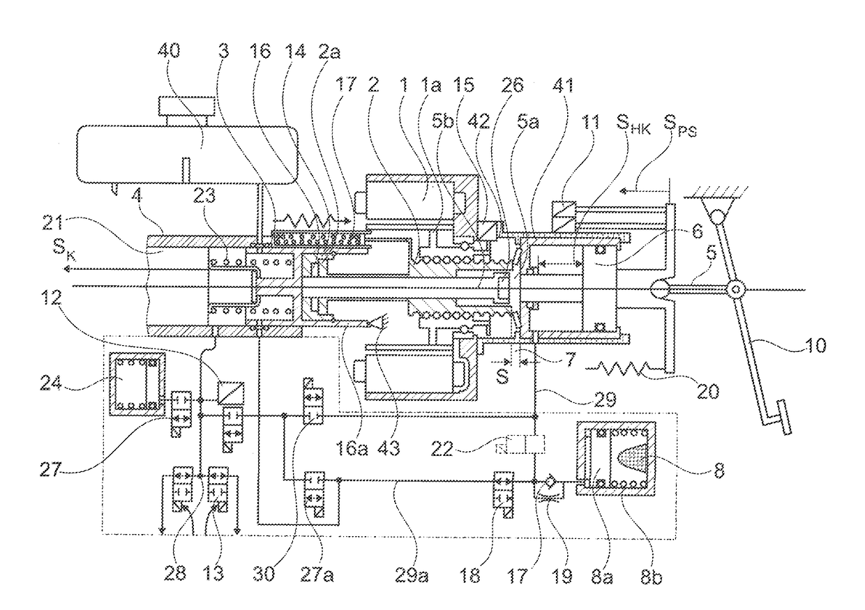
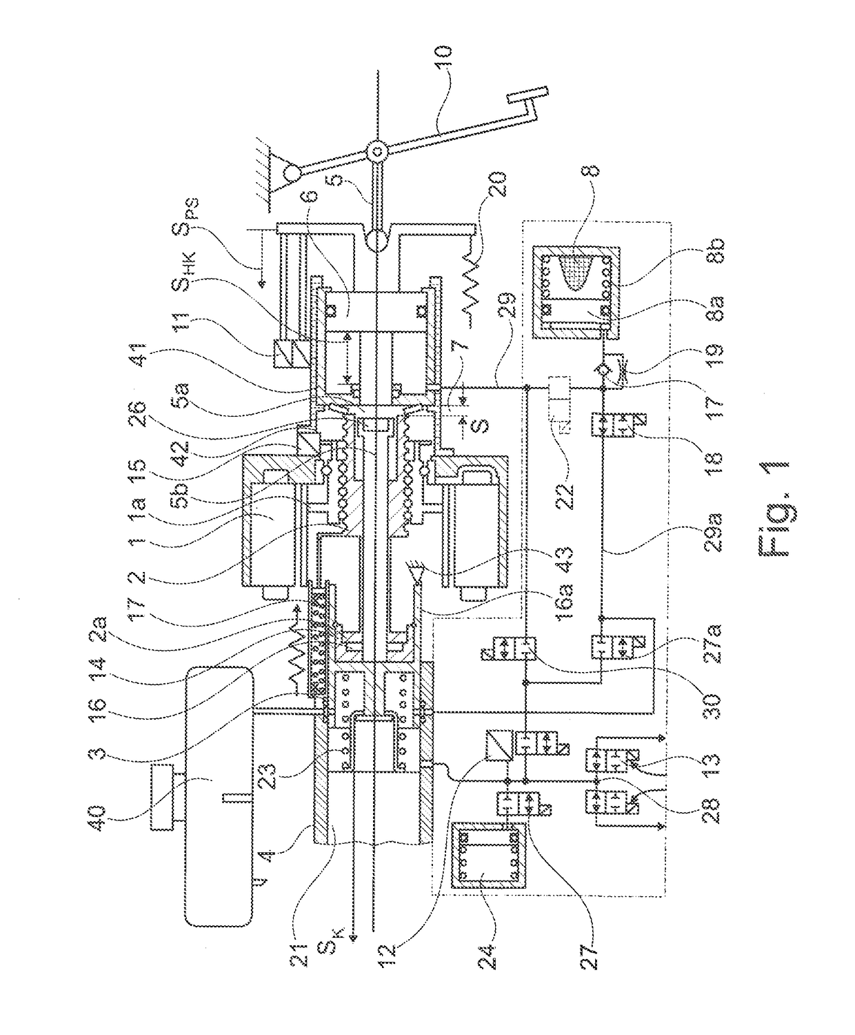
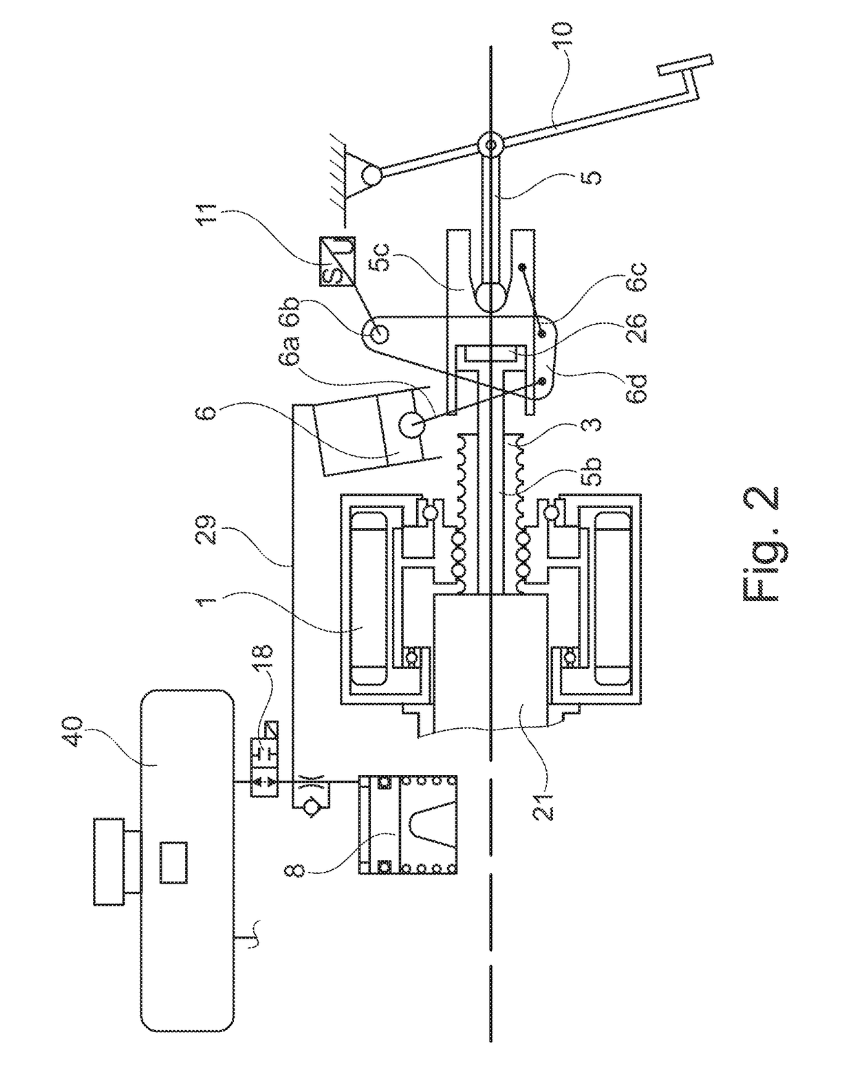
[0045]FIG. 1 shows in a transparent manner the configuration of the system with the known basic components such as electric motor 1, rotor with spindle nut 1a, spindle 2, push-rod piston 3, tandem main cylinder 4, return spring for push-rod piston 23, floating piston 21, 2× shutoff valves 13, (storage compartment 24 with 2 / 2 solenoid valve 27 according to DE 10 2009 055721 with push-rod piston brake circuit 28), engine position encoder 15 with redundant pedal travel sensors 11, brake pedal 10 with pedal tappet 5. These components are for example described in DE 10 2005 018649A1, reference to the full content of which is made here for the sake of simplicity.

[0046]The brake pedal 10 operates by means of the pedal tappet 5 on the auxiliary piston 6, wherein the volume displaced by this via a line 45 reaches the mechanical hydraulic travel simulator 8. With the movement of the auxiliary piston 6 the redundant pedal travel sensors 11 are connected, controlling the engine and at the same ...


PUM


Abstract

An actuating device for a vehicle brake system may include a first piston-cylinder unit, the at least one working space of which is to be connected to at least one wheel brake of the vehicle via at least one hydraulic line, an electromechanical drive device and an actuating device, in particular a brake pedal. Methods for operating a vehicle brake system including such an actuating device and for diagnosing various portions of a vehicle brake system (e.g., but not limited to, a feed valve or a travel simulator) are also presented.

Description

CROSS-REFERENCE TO RELATED APPLICATIONS[0001]This Application is a divisional application of U.S. patent Ser. No. 13 / 883,971, filed on May 7, 2013, which is a National Stage of PCT International Application No. PCT / EP2011 / 004476, filed on Sep. 6, 2011, and claims priority of German Patent Application No. 10 2010 050 133.6, filed on Nov. 3, 2010 and German Patent Application No. 10 2010 045 617.9, filed on Sep. 17, 2010. The disclosures of the aforementioned applications are incorporated herein by reference in their entirety.FIELD OF ENDEAVOR[0002]The present invention relates to an actuating device for a vehicle brake system, comprising a first piston-cylinder unit, the at least one working space of which is to be connected to at least one wheel brake of the vehicle via at least one hydraulic line, further comprising an electromechanical drive device and an actuating device, in particular a brake pedal.STATE OF THE ART[0003]Brake systems of the brake-by-wire type use a travel simula...

Claims


Application Information

Patent Timeline
Patent Type & Authority Applications(United States)
IPC IPC(8): B60T13/74B60T7/04B60T8/40B60T13/68
CPCB60T8/4077B60T13/686B60T13/745B60T13/74B60T7/042
Inventor LEIBER, HEINZUNTERFRAUNER, VALENTIN
Owner IPGATE
Learn More