
Optical imaging system

an optical imaging and optical technology, applied in the field of optical imaging systems, can solve the problems of reducing imaging quality and unsatisfactory imaging quality in wide angle observation, and achieve the effect of short installation length and high imaging quality

Active Publication Date: 2016-04-05
CARL ZEISS MEDITEC AG
View PDF17 Cites 0 Cited by
  • Summary
  • Abstract
  • Description
  • Claims
  • Application Information

AI Technical Summary

Benefits of technology

This configuration achieves high-contrast, high-quality imaging with minimal chromatic angle deviation, allowing for efficient observation across the entire wavelength range while maintaining a short installation length, thus enhancing the user's ability to observe objects like the eye without hindrance.

Problems solved by technology

A disadvantage of this microscope is that the imaging quality in the wide angle observation is not ideal.
The wide angle optical unit can be adapted to the microscope via a further reduction optical unit which can be introduced into the beam path; however, this is linked to the disadvantage of a reduced imaging quality.

Method used


Image

  • Optical imaging system
  • Optical imaging system
  • Optical imaging system

Examples


Embodiment Construction

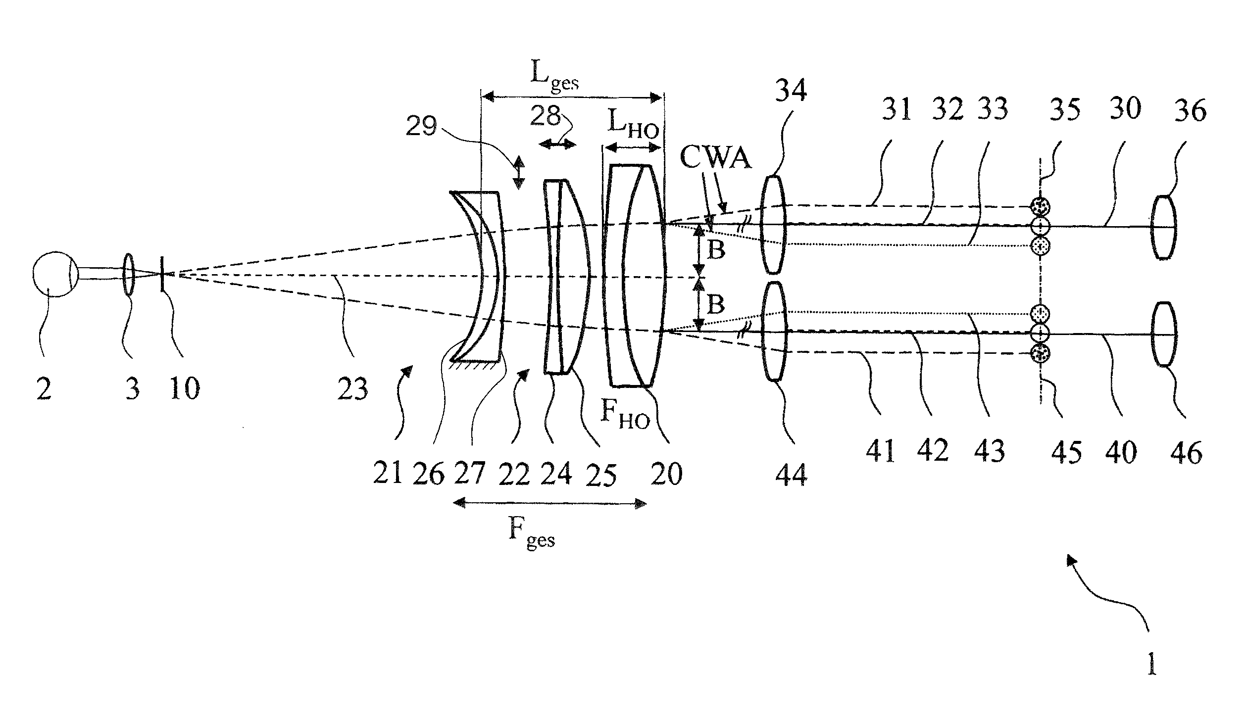
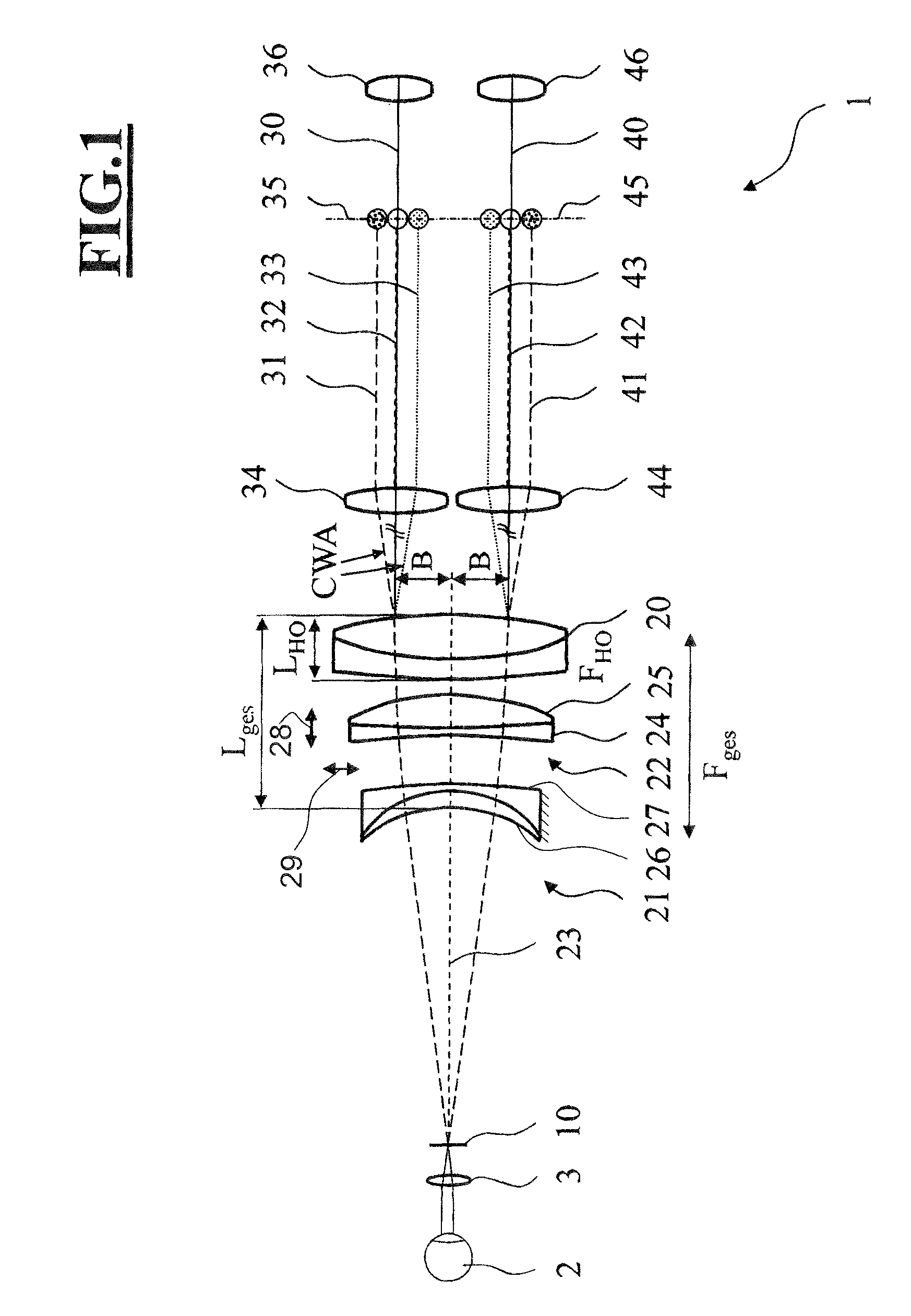
[0034]FIG. 1 depicts an exemplary embodiment of an optical imaging system 1 according to the invention, including a reduction optical unit mounted upstream of a main objective 20.

[0035]The exemplary embodiment shows an optical imaging system 1 for observing an eye 2. The optical imaging system 1 is configured as a stereoscopic observation system with a right-hand observation beam path 30 and a left-hand observation beam path 40 and includes a main objective 20 with an optical axis 23, a right-hand tube lens 34, a left-hand tube lens 44 and a right-hand eyepiece 36 and a left-hand eyepiece 46. It may comprise further optical elements not depicted here.

[0036]A further optical element in the form of an ophthalmic lens 3 and a reduction optical unit have been introduced into the beam path between the main objective 20 and the eye 2. The reduction optical unit includes a first composite element 22 and a second composite element 21.

[0037]The first composite element 22 disposed directly up...


PUM


Abstract

An optical imaging system generates an image of an object plane and includes a lens system which, in turn, includes a main objective and a reduction optical unit between the main objective and the object plane. The reduction optical unit includes a first composite element with a positive refractive power and a second composite element with a negative refractive power. The first composite element includes a first and second lens. The second composite element includes a third and fourth lens. An object-side first main plane and an image-side second main plane are defined by the lens system. The optical imaging system defines an observation beam path which is guided through the lens system so that, in each of the first main plane and the second main plane, the observation beam path is at a distance from the optical axis of the lens system.

Description

CROSS REFERENCE TO RELATED APPLICATION[0001]This application claims priority of German patent application no. 10 2013 219 383.1, filed Sep. 26, 2013, the entire content of which is incorporated herein by reference.FIELD OF THE INVENTION[0002]The invention relates to an optical imaging system, in particular a microscope, for generating an image of an object plane, including a lens system which includes a main objective and a reduction optical unit between the main objective and the object plane and which is aligned along an optical axis. The reduction optical unit includes a first composite element with a positive refractive power and a second composite element with a negative refractive power. The first composite element is disposed between the main objective and the second composite element. The first composite element includes a first lens and a second lens. The second composite element includes a third lens and a fourth lens. An object-side first main plane and an image-side seco...

Claims


Application Information

Patent Timeline
Patent Type & Authority Patents(United States)
IPC IPC(8): G02B21/00A61B3/12G02B21/02G02B21/22
CPCG02B21/0012A61B3/12G02B21/02G02B21/22
Inventor MERZ, FRANZHOEGELE, ARTUR
Owner CARL ZEISS MEDITEC AG
Learn More