
Method for producing an electrochemical bundle for a metal-ion accumulator comprising metal foam at the ends of foils

a technology of metal foam and electrochemical bundle, which is applied in the direction of wound/folded electrode electrodes, cell components, sustainable manufacturing/processing, etc., can solve the problems of inability to optimize the weight and volume of the accumulator in the end, difficulty in filling the electrochemical bundle of the lithium accumulator with electrolyte, and inability to meet the requirements of current distribution, etc., to achieve simple implementation and ensure good performance

Inactive Publication Date: 2018-06-21
COMMISSARIAT A LENERGIE ATOMIQUE ET AUX ENERGIES ALTERNATIVES
View PDF3 Cites 3 Cited by
  • Summary
  • Abstract
  • Description
  • Claims
  • Application Information

AI Technical Summary

Benefits of technology

The patent describes a process for making a metal foam strip that can be used in batteries. The process involves spooling the foam and welding it onto a metal strip to create a high-quality weld. The use of foam is advantageous because it allows for good heat removal and allows for easy filling with electrolyte. The process is simple and can be done in parallel, saving time and avoiding additional steps. The technical effect is a high-quality metal foam strip that can be used in batteries.

Problems solved by technology

Firstly, the weight and volume of the lateral uncoated electrode bands (margins) required for the electrical connection with the current collectors according to the prior art are not necessarily optimized, thereby implying that the weight and volume of the accumulator will in the end also not be optimized.
This therefore creates non-uniformities in current distribution, this possibly being, disadvantageous in particular for high-power applications of the accumulator.
Lastly, the step of filling a lithium accumulator electrochemical bundle with electrolyte may prove to be relatively long and tricky because the current collectors according to the prior art, such as they are welded to the accumulator electrochemical bundle margins, form a substantial obstacle to the passage of the electrolyte.
However, its implementation may prove to be constraining in certain applications.
This technique is relatively easy to implement, but ineffective in terms of electrical conductivity and removal of heat from the bundle;
This technique, which consists in increasing the density of the uncoated lateral bands (margins) is effective in terms of electrical conductivity and removal of the heat from the bundle, but more complicated to implement.

Method used


Image

  • Method for producing an electrochemical bundle for a metal-ion accumulator comprising metal foam at the ends of foils
  • Method for producing an electrochemical bundle for a metal-ion accumulator comprising metal foam at the ends of foils
  • Method for producing an electrochemical bundle for a metal-ion accumulator comprising metal foam at the ends of foils

Examples


Embodiment Construction

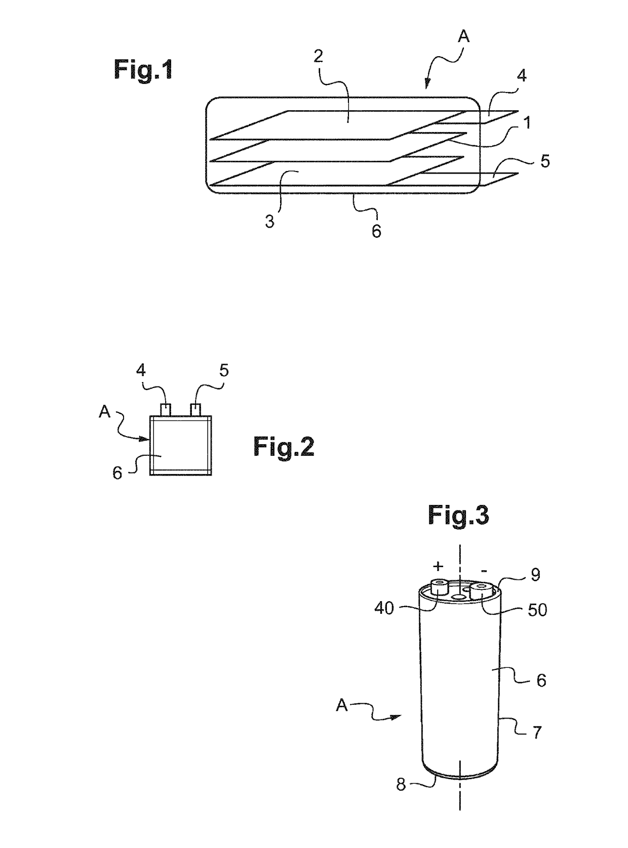
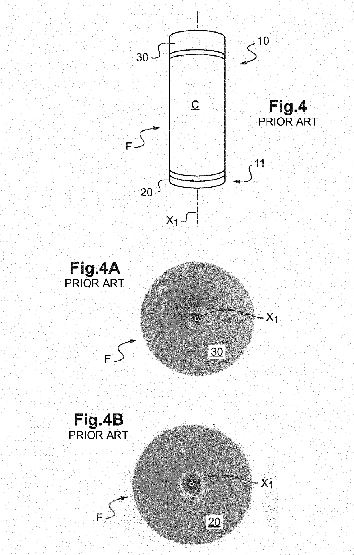
[0082]Other advantages and features of the invention will become more clearly apparent on reading the detailed description of examples of implementation of the invention, which nonlimiting description is given by way of illustration with reference to the following figures, in which:

[0083]FIG. 1 is an exploded schematic perspective view showing the various elements of a lithium-ion accumulator;

[0084]FIG. 2 is a front view showing a lithium-ion accumulator with its flexible packaging according to the prior art;

[0085]FIG. 3 is a perspective view of a lithium-ion accumulator according to the prior art with its rigid packaging consisting of a casing;

[0086]FIG. 4 is a perspective view of an electrochemical bundle of a lithium-ion accumulator according to the prior art, the bundle consisting of a single electrochemical cell wound upon itself by spooling;

[0087]FIG. 4A is a photographic top view of one lateral end of the electrochemical bundle in FIG. 4;

[0088]FIG. 4B is a photographic top vi...


PUM

PropertyMeasurementUnit
voltageaaaaaaaaaa
diameteraaaaaaaaaa
diameteraaaaaaaaaa

Abstract

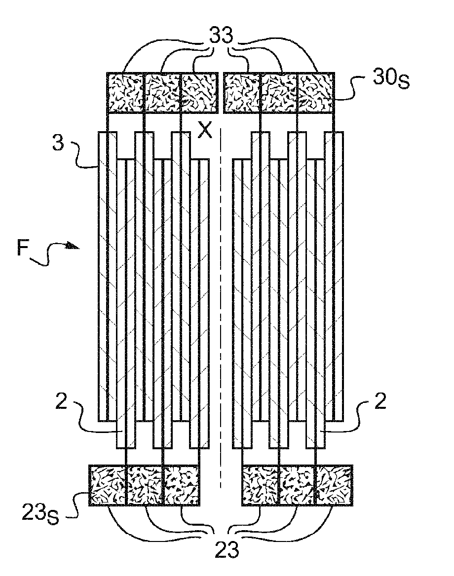
One subject of the invention is a process for producing an electrochemical bundle of a metal-ion accumulator, with a view to its electrical connection to the output terminals of the accumulator, which is characterized by the addition of a strip of metal foam to the margins with a view to welding with a current collector.

Description

TECHNICAL FIELD[0001]The present invention relates to the field of metal-ion electrochemical generators, which operate according to the principle of insertion or deinsertion, or in other words intercalation / deintercalation, of metal ions in at least one electrode.[0002]More particularly it relates to a metal-ion electrochemical accumulator including at least one electrochemical cell consisting of an anode and a cathode on either side of a separator impregnated with electrolyte, two current collectors one of which is connected to the anode and the other to the cathode, and a casing of a shape that is elongate along a longitudinal axis (X), the casing being arranged to sealably house the electrochemical cell even though a portion of the current collectors forming output terminals, also referred to as poles, passes therethrough.[0003]The separator may consist of one or more films.[0004]The casing may include a cover and a container, usually referred to as a can, or include a cover, a b...

Claims


Application Information

Patent Timeline
Patent Type & Authority Applications(United States)
IPC IPC(8): H01M2/26H01M4/133H01M4/136H01M4/131H01M10/0525H01M10/04H01M10/0587H01M50/528
CPCH01M2/263H01M4/133H01M4/136H01M4/131H01M10/0525H01M10/0422H01M10/0431H01M10/0587Y02E60/10Y02P70/50
Inventor MASSON, OLIVIER
Owner COMMISSARIAT A LENERGIE ATOMIQUE ET AUX ENERGIES ALTERNATIVES
Learn More