
Argon arc preheating wire welding method

A technology of welding wire and argon arc, applied in the direction of arc welding equipment, welding equipment, manufacturing tools, etc., can solve heating and other problems

Inactive Publication Date: 2007-09-05
HARBIN INST OF TECH
View PDF3 Cites 2 Cited by
  • Summary
  • Abstract
  • Description
  • Claims
  • Application Information

AI Technical Summary

Problems solved by technology

The invention adopts the arc protected by argon gas as the heating source to heat the welding wire, and adopts the arc as the heat source, which solves the problem that the traditional resistance heat source cannot heat materials with high conductivity (such as copper and aluminum); , to avoid oxidation of the heated wire

Method used


Image

  • Argon arc preheating wire welding method

Examples


specific Embodiment approach 1

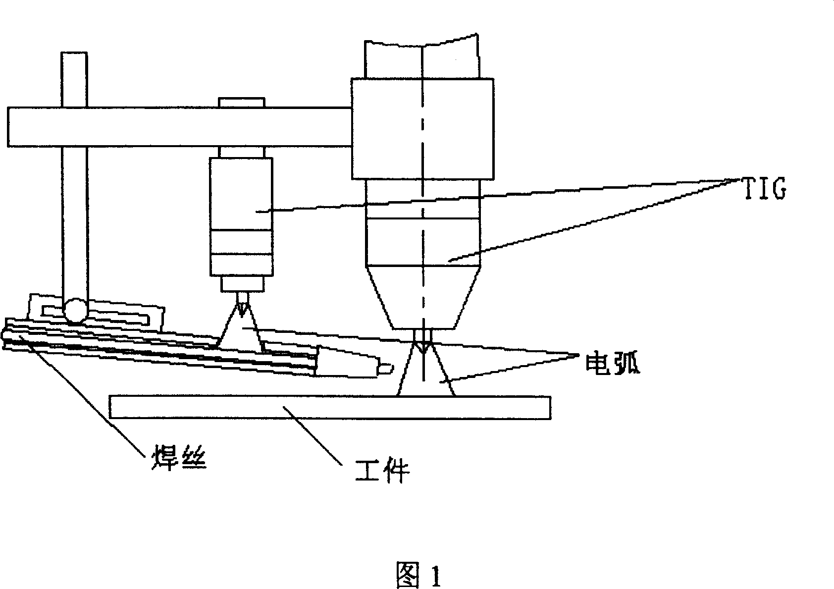
[0005] Specific implementation mode 1: In this implementation mode, the welding wire is preheated in this way: the arc protected by argon gas is used as the heating source, and one end of the TIG power supply with controllable output current is connected to the gun, and the other end is connected to the wire feeder to feed At the wire nozzle, an arc is ignited to heat the welding wire.

specific Embodiment approach 2

[0006] Embodiment 2: In this embodiment, the method for preheating the welding wire will be described in detail with reference to FIG. 1 . This embodiment adopts the arc of TIG protected by argon gas as the heating heat source. As shown in Figure 1, two TIG welding torches are installed on the support frame. The right torch in the figure is used to weld the workpiece, and the middle torch passes through the small window on the wire feeder The ignition arc heats the welding wire to form the argon arc hot wire TIG technology.


PUM


Abstract

A method for preheating the welding wire used for TIG welding in order to increase the speed and quality of welding features that the argon arc is used as the heat source, the output current controllable TIG power supply is electrically connected across the weld gun and the feeding mouth of welding wire, and the argon arc is triggered to preheat the welding wire.

Description

Technical field: [0001] The invention relates to the improvement of the heating method of the traditional TIG welding hot wire. Background technique: [0002] In traditional hot wire TIG welding, the method of resistance heating is often used to heat the welding wire, that is, the welding wire is used as a part of the circuit. When a current flows in it, the welding wire generates resistance heat, so the welding wire is preheated. This process is suitable for welding carbon steel, stainless steel and other materials. These materials have high resistivity and the effect is obvious, but it is difficult to apply to the welding of high conductivity materials such as copper and aluminum. At present, copper and aluminum materials are widely used in national defense and other fields, and the hot wire TIG welding technology suitable for these materials is undoubtedly of great significance to production. Invention content: [0003] In order to solve the problem of hot-wire TIG wel...

Claims


Application Information

Patent Timeline
Patent Type & Authority Patents(China)
IPC IPC(8): B23K9/235B23K9/16
Inventor 吕世雄杨士勤杨春利王海涛卢昌福
Owner HARBIN INST OF TECH
Learn More