Method and apparatus for optimizing blocking grating for cone beam ct image scattering correction

a cone beam and scattering correction technology, applied in the field of medical imaging, can solve the problems of affecting the accuracy of the ct value, the quality of the cone beam computed tomography image will be rapidly deteriorated, and the scattering photons cannot be modelled into the traditional ct reconstruction theory, so as to achieve accurate extraction of the scattering signal

Active Publication Date: 2018-05-17
SHENZHEN INST OF ADVANCED TECH
View PDF21 Cites 1 Cited by
  • Summary
  • Abstract
  • Description
  • Claims
  • Application Information

AI Technical Summary

Benefits of technology

[0010]An objective of the present disclosure is to provide a method and apparatus for optimizing a blocking grating for cone beam CT image scattering correction, so as to solve the existing problem that the number of scans is increased and it is difficult to accurately extract a scattering signal when the scattering correction is performed using a blocker.

Problems solved by technology

However, in accompany with the expansion of irradiation volume in a single projection, the quality of the cone-beam computed tomography (CBCT) image will be rapidly deteriorated due to the restriction of a fundamental physical process—scattering pollution.
The scattered photons deviate from the incident beam direction and cannot be modelled into the traditional CT reconstruction theory, which is the error source of the CT image reconstruction.
The CBCT scattering pollution seriously affects the precision of the CT value, the detectability of the target with a low contrast, and the accuracy of the dose calculation, and those disadvantages directly disable the CBCT for wide clinical applications.
When a human body is scanned in a CBCT system having no scattering correction, the CT value error caused by the scattering artifact can reach 350 HU, thus the CBCT is mainly used for the primary localization and positioning, and its further applications in the intervention and radiotherapy are seriously restricted.
But the method is restricted by the physical space of the CBCT device itself, while requiring adding the X-ray dose to compensate for the increase of the distance, thus it is not practical in clinical practices.
The method has the defect that the attenuation efficiency of the scattered light is not high.
Currently, the commercial grid only provides an SPR reduction rate of about 3 times, and cannot ensure the quality of the CBCT image under the high scattering environment.
Since it is impossible to theoretically predict the random scattering time, the scattering noises still remain in the image even a perfect pre-processing method is used.
But correspondingly, the scattering estimation accuracy is limited and the parameters shall be tediously adjusted for a complex object.
But the method has a huge calculation amount, thus much time is cost, and the current computer computing power restricts its application in the CBCT image reconstruction that almost requires a real time processing.
The method does not increase the patient exposure dose or scanning time, but the clinical application effect is restricted by actual physical factors, such as the spiral arm vibration and big focus size.
The measurement-based method can obtain an accurate scattering estimation, but the cost is the loss of the source signal.
Most of the existed scattering correction methods using the blocker need to scan twice to compensate for the blocked original projection signal, and they cannot be put into the clinical application since the patient's expose dose is increased.
In addition, those methods are used in the desktop CBCT experimental platform; since such experimental platform replaces the rotation of the light source and the detector with the rotation of the object to be scanned, the isocenter of the CT system is stable, and the projection positions of the blocker at different timing are almost consistent with each other, thus the difficulty for performing a scattering correction using the blocker is largely decreased, and those methods are only applicable for the lab desktop CBCT system with a stable isocenter.
However, in the clinical CBCT system, due to the vibration in the rack rotation process and the deviation of the rotation isocenter, the projection position of the blocking grating varies with the rotation of the rack, and it is difficult to accurately extract the scattering signal in the grating area.

Method used


Image

  • Method and apparatus for optimizing blocking grating for cone beam ct image scattering correction
  • Method and apparatus for optimizing blocking grating for cone beam ct image scattering correction
  • Method and apparatus for optimizing blocking grating for cone beam ct image scattering correction

Examples


Embodiment Construction

[0021]Next, the technical solutions in the embodiments of the present disclosure will be clearly and completely described with reference to the drawings in the embodiments of the present disclosure. Obviously, those described are just a part rather than all of the embodiments of the present disclosure. Based on the embodiments of the present disclosure, any other embodiment obtained by a person skilled in the art without paying any creative effort shall fall within the protection scope of the present disclosure.

[0022]As known to a person skilled in the art, the embodiment of the present disclosure may be implemented as a system, an apparatus, a device, a method or a computer program product. Thus the present disclosure can be specifically implemented as complete hardware, complete software (including firmware, resident software, microcode, etc.), or a combination of hardware and software.

[0023]Next, the principle and spirit of the present disclosure are elaborated in details as foll...


PUM


Abstract

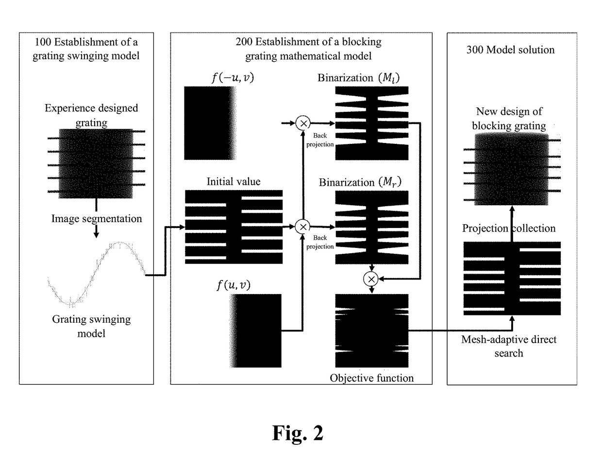
A method and apparatus for optimizing a blocking grating for cone beam CT image scattering correction, wherein the method comprises: scanning a blocking grating to establish a swinging model thereof; setting initial coordinates of the blocking grating along a longitudinal direction of a detector in an initial projection, and establishing an objective function between CBCT image data missing voxel values and the coordinates of the blocking grating along the longitudinal direction of the detector according to the swinging model; minimizing the objective function with a mesh-adaptive direct search algorithm to generate optimized coordinates of the blocking grating along the longitudinal direction of the detector. The present disclosure proposes a brand new scattering correction method not requiring any source compensation, performs a mathematical optimization modeling of the data missing caused by the blocking grating in the image domain, quantitatively evaluates the influence on the reconstructed image by a blocker, solves a geometric optimal structure of the blocker using a mesh-adaptive direct search algorithm, and lays a solid theory foundation for the scattering correction method based on the blocker measurement.

Description

TECHNICAL FIELD[0001]The present disclosure relates to the field of medical imaging related to cone beam CT applications, and particularly, to a method and apparatus for optimizing a blocking grating for cone beam CT image scattering correction.BACKGROUND[0002]This section intends to provide a background or context for the embodiments of the present disclosure described in the claims. Although being included in this section, the descriptions herein will not be deemed as the prior art.[0003]The technology of Image Guide Radiation Therapy (IGRT) is the most important means in the precise radiotherapy at present. The IGRT can provide exact position information for precise lesion localization and tumor irradiation, and has been widely used in the modern minimally invasive surgery and radiotherapy. The X-ray CBCT installed beside the treatment couch is an important means for implementing image guide nowadays.[0004]However, in accompany with the expansion of irradiation volume in a single...

Claims


Application Information

Patent Timeline
Patent Type & Authority Applications(United States)
IPC IPC(8): A61B6/00A61B6/03G01T1/161
CPCA61B6/4291A61B6/032A61B6/4085A61B6/5205A61B6/5282G01T1/161A61B6/542A61B6/583A61N5/1049A61N2005/1061A61B6/035A61B6/06A61B6/40A61B6/42A61B6/4208A61B6/4233A61B6/44A61B6/4429A61B6/4435A61B6/4441A61B6/4447A61B6/482A61B6/483A61B6/52A61B6/5211A61B6/5258A61B6/54A61B6/545A61B6/58A61B6/582
Inventor LIANG, XIAOKUNXIE, YAOQINZHANG, ZHICHENGNIU, TIANYE
Owner SHENZHEN INST OF ADVANCED TECH
Why Eureka
Try Eureka