Method and apparatus for suppressing an acoustic interference signal in an incoming audio signal

Active Publication Date: 2005-09-27
SIVANTOS PTE LTD
View PDF18 Cites 44 Cited by
  • Summary
  • Abstract
  • Description
  • Claims
  • Application Information

AI Technical Summary

Benefits of technology

[0014]A further advantage of the method is the direction-dependent suppression of an interference signal, since the method makes it possible to deliberately filter from the directional microphone signal interference signals that are received from the direction with a minimum sensitivity.
[0016]In an embodiment of the method, the weighting is determined so as to minimize the sensitivity of the directional microphone system for an interference signal source that is located in one direction with respect to the directional microphone system. The more accurately the sensitivity minimum can be placed in one direction the more accurately the interference signals from localized interference signal sources can be suppressed.
[0018]In order to determine a weighting, a signal source which is located in one direction with respect to the directional microphone system is, for example, removed from the directional microphone signal as well as possible by variation of the weighting of the microphone signals. The weightings determined in this way have the advantage that they are produced in controlled conditions and with a fine resolution, in each case optimized to the incidence direction of the signal source.
[0021]In another embodiment, the value of the weighting during the production of the two or more directional microphone signals is changed in order to successively produce directional microphone signals with different direction-dependent sensitivities. This has the advantage that there is no need to simultaneously calculate a large number of directional microphone signals.

Problems solved by technology

Matching which is carried out in open air, however, is partially corrupted again by the influence of the head on the sound propagation during operation of a directional microphone system which is used, for example, in a hearing aid.

Method used


Image

  • Method and apparatus for suppressing an acoustic interference signal in an incoming audio signal
  • Method and apparatus for suppressing an acoustic interference signal in an incoming audio signal
  • Method and apparatus for suppressing an acoustic interference signal in an incoming audio signal

Examples


Embodiment Construction

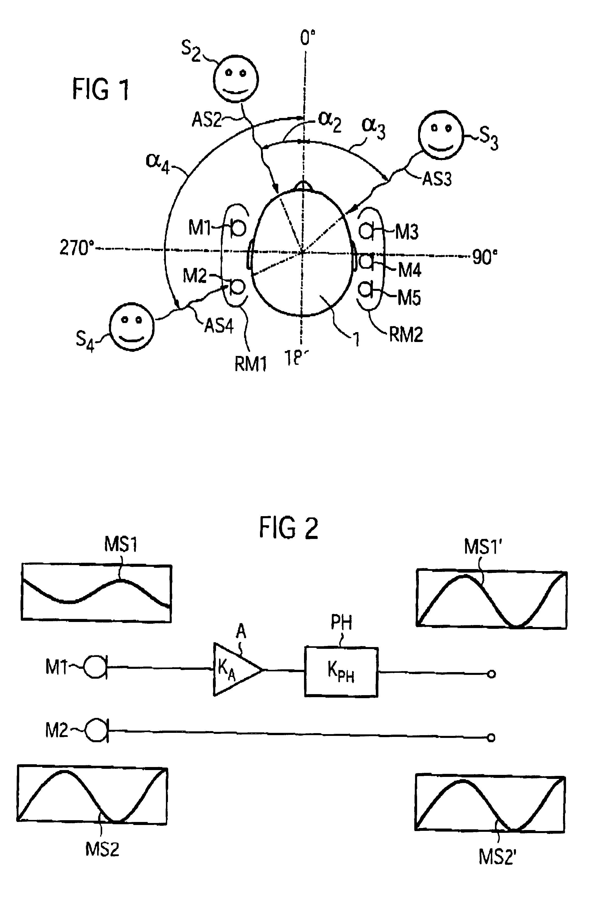
[0031]FIG. 1 shows a typical example of the use of a directional microphone system RM1, RM2 for the suppression of acoustic interference signals. In this case, one or more directional microphone systems RM1, RM2 are located in a hearing aid, which is used as such by the person 1. The person 1 is having a conversation with a person S2, who is located in the direction region of the directional microphone system RM1, RM2. The direction region is in the straight-ahead direction, which is to say in the direction of the axis that is denoted by 0°. The discrepancy between the position of the person S2 and the 0° axis through the angle a2 is, for example, within a conical direction region of the directional microphone system RM1.

[0032]In addition to the person S2, there are two other people S3, S4 within the vicinity of person 1. The people, S3, S4 are conversing with one another, that is to say they represent interference signal sources which are located at respective angles of α3 and α4 w...


PUM


Abstract

In order to suppress at least one interference signal in an incoming audio signal using a directional microphone system having at least two microphones, that directional microphone signal which has the lowest interference signal component is selected from two or more directional microphone signals that have been produced by weighted combination from the signals of the microphones, with the weighting in each case determining a direction-dependent sensitivity. If a sensitivity distribution has a minimum in the direction of the interference signal source, then a low signal energy is detected, which characterizes a lower interference signal component.

Description

BACKGROUND OF THE INVENTION[0001]1. Field of the Invention[0002]The present invention concerns a method for suppressing at least one acoustic interference signal by using a directional microphone system that has at least two microphones, and to an apparatus for implementing the method.[0003]2. Description of the Prior Art[0004]The matching of microphones in a directional microphone system is of significant importance for the suppression of interference signals.[0005]In the case of steady-state matching, the microphones in a directional microphone system are matched to one another in the steady state in open air. This matching process is generally carried out using a measurement device that allows amplitude matching and phase matching of the individual, generally omnidirectional, microphones to be carried out. Steady-state matching allows a diffuse interference sound field to be eliminated from the directional microphone signal. Matching which is carried out in open air, however, is ...

Claims


Application Information

Patent Timeline
IPC IPC(8): H04R3/00H04R25/00H04R29/00
CPCH04R3/005H04R29/006H04R25/407H04R2430/03
Inventor FISCHER, EGHART
Owner SIVANTOS PTE LTD
Why Eureka
Try Eureka