
High fidelity, professional grade microphone system for direct coupling to recording components

a microphone system and high-fidelity technology, applied in the field of high-fidelity microphones, to achieve the effect of high gain, convenient direct connection, and high fidelity

Active Publication Date: 2018-03-22
GOEKE WADE
View PDF7 Cites 3 Cited by
  • Summary
  • Abstract
  • Description
  • Claims
  • Application Information

AI Technical Summary

Benefits of technology

The present invention aims to provide a high fidelity microphone system with improved performance compared to existing technologies. The invention achieves this by reducing the number of components needed for professional audio mic’ing setups, providing higher flexibility in application and interfacing with professional audio equipment, reducing or eliminating redundancy in professional audio components, and retaining the basic form factors for professional audio mics. These improvements result in cost savings and reduced economic impact when multiple mics are used.

Problems solved by technology

As is understood by those skilled in the art, this can involve a plurality of sometimes subtle factors that may not allow of predictable results.

Method used


Image

  • High fidelity, professional grade microphone system for direct coupling to recording components
  • High fidelity, professional grade microphone system for direct coupling to recording components
  • High fidelity, professional grade microphone system for direct coupling to recording components

Examples


embodiment 40

[0164]A dual triode design using a single dual triode tube such as a 12zx7, allows a simpler, more cost effective, easier to design, and lower heat application in this embodiment 40 of the invention in FIG. 4.[0165]1) Gain should be distributed evenly between pre amplifier 42B and line amplifier stage 42C. In this case using two triodes in cascade may allow the gain to be spread somewhat more evenly between the stages than the Pentode version of FIG. 3.[0166]2) Input amplifier 42 must function as both the buffer 42B (Part 1) as on a standard microphone but also a variable gain amplifier 42B (Part 2) as on a pre amp, as noted below.[0167]A) In this tube circuit, for example, two medium gain triodes in cascade are designed to have very high impedance and where gain is controllable through negative feedback.[0168]B) Impedance of the input stage 42B must be extremely high to avoid loading the capsule 42A but also to avoid interaction of the gain control with the capsule. In classic tube...

embodiment 90

[0287]It can therefore be seen that in embodiment 90 the user has a variety of local control options for mic set up and performance.

[0288]H. External Power Supply Example (FIGS. 10A-10C)

[0289]With specific reference to these figures, one example of an external power supply 71A is shown. As indicated in FIG. 10A, it can be of easily portable size with carrying handle 103. It can include an “on” indicator light. Its case or housing 102 can be on the order of several inches in height and width and perhaps a foot or so in depth or length.

[0290]FIG. 10B further indicates there can be plural output ports 104 and 105 (or more), although one may be all that is needed for a cord to microphone 90. But the option of a variety of ports can provide flexibility regarding connectors. It also would make the power supply available not only for mic 90 but other components if needed.

[0291]Another feature, over and above being an external and portable power supply 71A for mic 90, is auxiliary controls ...


PUM


Abstract

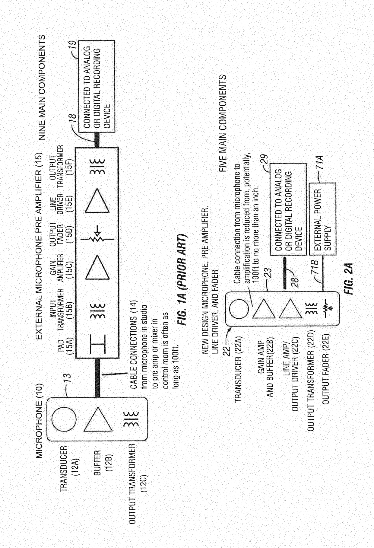
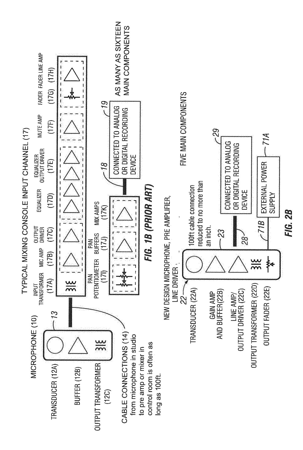
Current microphone designs are still using concepts developed in the early 20th century. A transducer followed by a simple buffer with high impedance, low power, and low gain. Even when tubes were replaced by solid state devices the same practice continued, with the low gain triode being replaced by an even smaller power, lower current FET buffer. The invention offers a microphone system intended for professional audio applications that dispenses with these, low power concepts and incorporates elements of a microphone, microphone pre amplifier, and high power mixing console / pre amp line drivers into a single housing. By combining transducer, high fidelity pre amp circuit, and high power line driving stage with a high voltage, high current external power supply, the capabilities of microphones can be greatly increased in many ways. Our approach can be implemented in a variety of circuit topologies including discrete transistors, tubes and integrated circuits, our concept allows microphones to connect directly to analog or digital recording devices without the need for external mixers or pre amplifiers. The design not only allows for unprecedented simplicity in the work flow of the modern recording studio, which combines the use of stand-alone analog records, standalone digital recorder, and computer workstation based recording options, but also eliminates redundant circuits that are present in microphones, microphone pre amps, and mixing consoles, while offering the customer increased value.

Description

CROSS-REFERENCE TO RELATED APPLICATIONS[0001]This application claims the benefit of Provisional Application U.S. Ser. No. 62 / 396,630 filed on Sep. 19, 2016, all of which is herein incorporated by reference in its entirety.I. BACKGROUND OF THE INVENTIONA. Field of the Invention[0002]The present invention relates to microphones and, in particular, high fidelity microphones such as used in professional audio settings.[0003]Current microphone designs are still using concepts developed in the early 20th century; a transducer followed by a simple buffer with high impedance, low power, and low gain. Even when tubes were replaced by solid state devices the same practice continued, with the low gain triode being replaced by an even smaller power, lower current FET buffer.[0004]The invention relates to a microphone system intended for professional audio applications that dispenses with these low power concepts and incorporates elements of a microphone, microphone pre amplifier, and high power...

Claims


Application Information

Patent Timeline
IPC IPC(8): H04R1/04H03G3/06H03G7/00H03G3/10H03G9/04H03G9/14
CPCH04R1/04H03G3/06H03G7/004H03G3/10H03G9/04H03G9/14H04R1/08H04R3/00
Inventor GOEKE, WADE
Owner GOEKE WADE
Learn More