
Surface-coated cutting tool in which hard coating layers exhibits excellent chipping resistance

a cutting tool and hard coating technology, applied in the direction of manufacturing tools, turning machine accessories, superimposed coating process, etc., can solve the problems of insufficient chipping resistance, decrease in toughness, etc., and achieve excellent toughness and wear resistance, and excellent chipping resistance and wear resistance.

Active Publication Date: 2018-03-15
MITSUBISHI MATERIALS CORP
View PDF0 Cites 2 Cited by
  • Summary
  • Abstract
  • Description
  • Claims
  • Application Information

AI Technical Summary

Benefits of technology

The present invention relates to a new hard coating layer for cutting tools that exhibits excellent toughness, wear resistance, and chipping resistance, even in high-speed intermittent cutting work of carbon steel, cast iron, alloy steel, or the like. The hard coating layer includes an upper layer with a relatively high Al amount and a lower layer with a relatively low Al amount, which exhibits a periodic compositional variation in the crystal grains. The hard coating layer also exhibits improved adhesion strength between the tool body, lower layer, and upper layer, which further improves chipping resistance and peeling resistance. The coated tool exhibits excellent cutting performance even in long-term use.

Problems solved by technology

Meanwhile, since the (Ti,Al)(C,N) layer which is an upper layer has a relatively higher Al amount, excellent wear resistance is obtained, but it cannot be said that chipping resistance is sufficient due to a decrease in toughness.

Method used


Image

  • Surface-coated cutting tool in which hard coating layers exhibits excellent chipping resistance
  • Surface-coated cutting tool in which hard coating layers exhibits excellent chipping resistance
  • Surface-coated cutting tool in which hard coating layers exhibits excellent chipping resistance

Examples


example 1

[0091]As raw material powders, a WC powder, a TiC powder, a TaC powder, an NbC powder, a Cr3C2 powder, and a Co powder, all of which had an average grain size of 1 to 3 μm, were prepared, and the raw material powders were mixed in mixing compositions shown in Table 1. Wax was further added thereto, and the mixture was blended in acetone by a ball mill for 24 hours and was decompressed and dried. Thereafter, the resultant was press-formed into green compacts having predetermined shapes at a pressure of 98 MPa, and the green compacts were sintered in a vacuum of 5 Pa at a predetermined temperature in a range of 1370° C. to 1470° C. for one hour. After the sintering, tool bodies A to C made of WC-based cemented carbide with insert shapes according to ISO standard SEEN1203AFSN were produced.

[0092]In addition, as raw material powders, a TiCN (TiC / TiN=50 / 50 in terms of mass ratio) powder, an Mo2C powder, a ZrC powder, an NbC powder, a WC powder, a Co powder, and an Ni powder, all of which...

example 2

[0117]Lower layers formed of (Ti,Al)(C,N) having a composition inclined structure in which the Al amount in the layer continuously increases from the tool body side towards the upper layer side, were deposited on the surfaces of the tool bodies A to C made of WC-based cemented carbide and the tool body D made of TiCN-based cermet produced in Example 1 through a thermal CVD method for a predetermined time using a chemical vapor deposition apparatus, under forming conditions A2 to C2 shown in Table 11. Specifically, immediately after starting the film forming, the lower layer is formed by continuously changing a gas flow rate of AlCl3 and TiCl4 while maintaining the total of an AlCl3 gas flow rate and a TiCl4 gas flow rate to be constant so that a proportion of the AlCl3 gas flow rate with respect to the total of the AlCl3 gas flow rate and the TiCl4 gas flow rate increases.

[0118]Next, present invention coated tools 11 to 17 shown in Table 12 were produced by depositing an upper layer...

example 3

[0134]Lower layers formed of (Ti,Al)(C,N) were deposited on the surfaces of the tool bodies A to C made of WC-based cemented carbide and the tool body D made of TiCN-based cermet produced in Example 1 through a thermal CVD method for a predetermined time using a chemical vapor deposition apparatus, under forming conditions A3 to C3 shown in Table 13.

[0135]Here, the lower layer is formed to have a layered structure including a plurality of layers of a first lower layer on the tool body side, a second lower layer substantially positioned at the center, and a third lower layer on the upper layer side, Al concentration is substantially constant in each layer, but the Al concentration of each layer stepwisely increases from the tool body side towards the upper layer side, from the first lower layer towards the third lower layer.

[0136]There is no limitation to the first to third lower layers, and the lower layer can have a configuration as a layered structure of n layers (here, n is integ...


PUM

PropertyMeasurementUnit
thicknessaaaaaaaaaa
thicknessaaaaaaaaaa
thicknessaaaaaaaaaa

Abstract

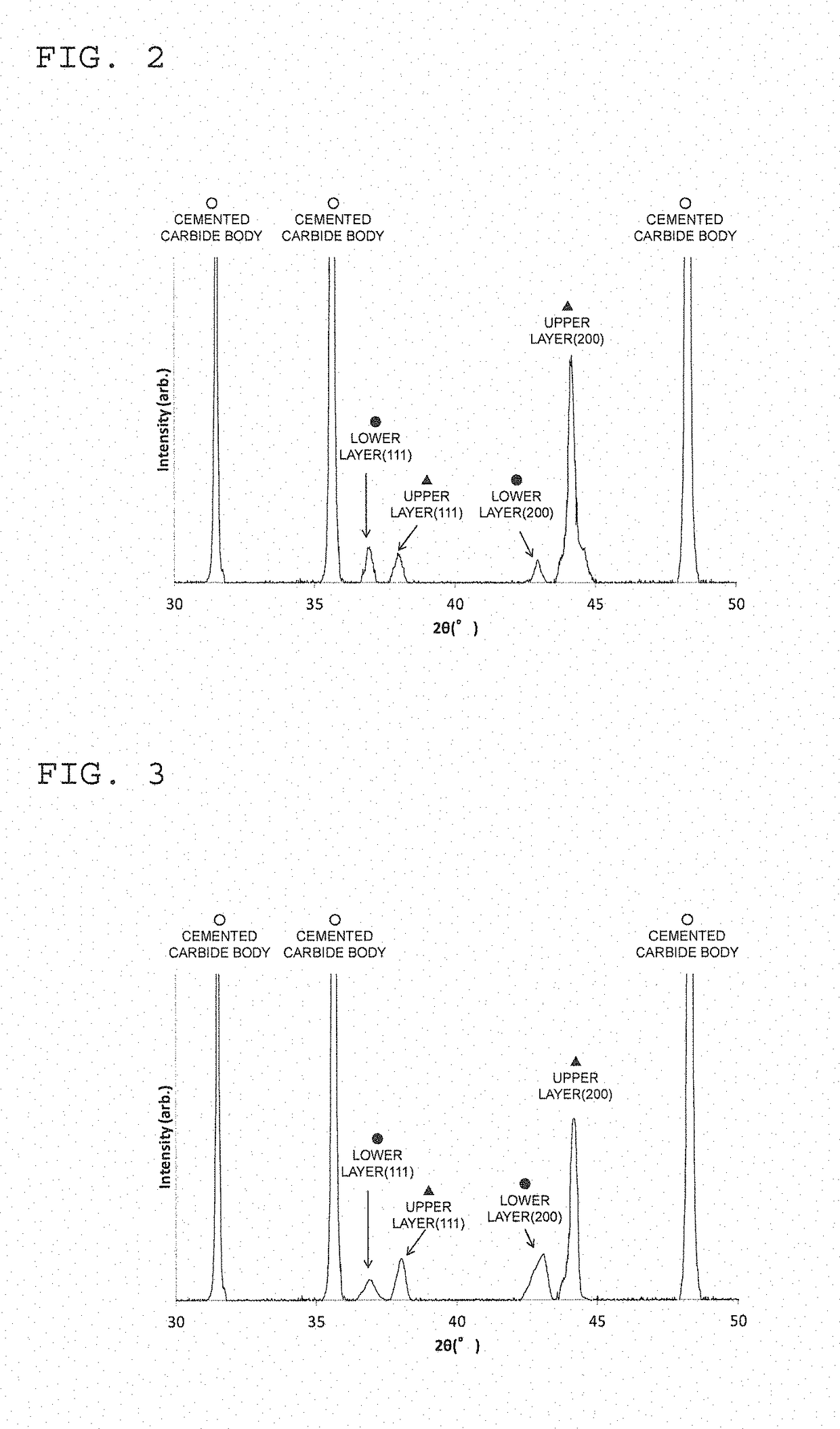
A coated tool includes a hard coating layer that is formed with a (Ti,Al)(C,N) layer on its surface, the layer including an upper layer where a periodic compositional variation in Ti and Al is present in crystal grains having an NaCl type face-centered cubic structure, and a lower layer where a periodic compositional variation in Ti and Al is not present. The upper layer has a high Al amount, while the lower layer has a low Al amount. A value of I(200) / I(111) of the upper layer is greater than 10 and that of the lower layer is less than 3. The lower layer has a composition inclined structure where the Al amount increases from a tool body side towards an upper layer side. The lower layer contains multiple layers, where the Al amount of each layer can increase from the tool body side towards the upper layer side.

Description

CROSS-REFERENCE TO RELATED PATENT APPLICATIONS[0001]This application is a U.S. National Phase Application under 35 U.S.C. § 371 of International Patent Application No. PCT / JP2016 / 057745, filed Mar. 11, 2016, and claims the benefit of Japanese Patent Applications No. 2015-050644, filed Mar. 13, 2015, and No. 2016-041383, filed Mar. 3, 2016, all of which are incorporated herein by reference in their entireties. The International Application was published in Japanese on Sep. 22, 2016 as International Publication No. WO / 2016 / 148056 under PCT Article 21(2).FIELD OF THE INVENTION[0002]The present invention relates to a surface-coated cutting tool (hereinafter, referred to as coated tool), in which a hard coating layer exhibits excellent chipping resistance during high-speed intermittent cutting work of carbon steel, cast iron, alloy steel or the like during which high-temperature heat is generated and impact loads are exerted on a cutting edge, and excellent cutting performance is exhibit...

Claims


Application Information

Patent Timeline
Patent Type & Authority Applications(United States)
IPC IPC(8): B23B27/14C23C16/34
CPCB23B27/14C23C16/347B23B2228/105C23C16/34C23C16/36C23C16/403C23C16/45523C23C28/042C23C28/044C23C28/42C23C30/005B23B2224/24B23C2224/24B23C2228/10
Inventor SATO, KENICHITATSUOKA, SHOYAMAGUCHI, KENJI
Owner MITSUBISHI MATERIALS CORP
Learn More