Hydrogen-releasing film
- Summary
- Abstract
- Description
- Claims
- Application Information
AI Technical Summary
Benefits of technology
Problems solved by technology
Method used
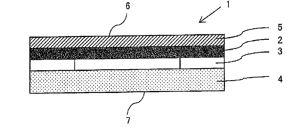
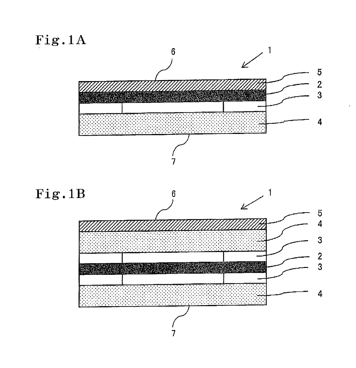
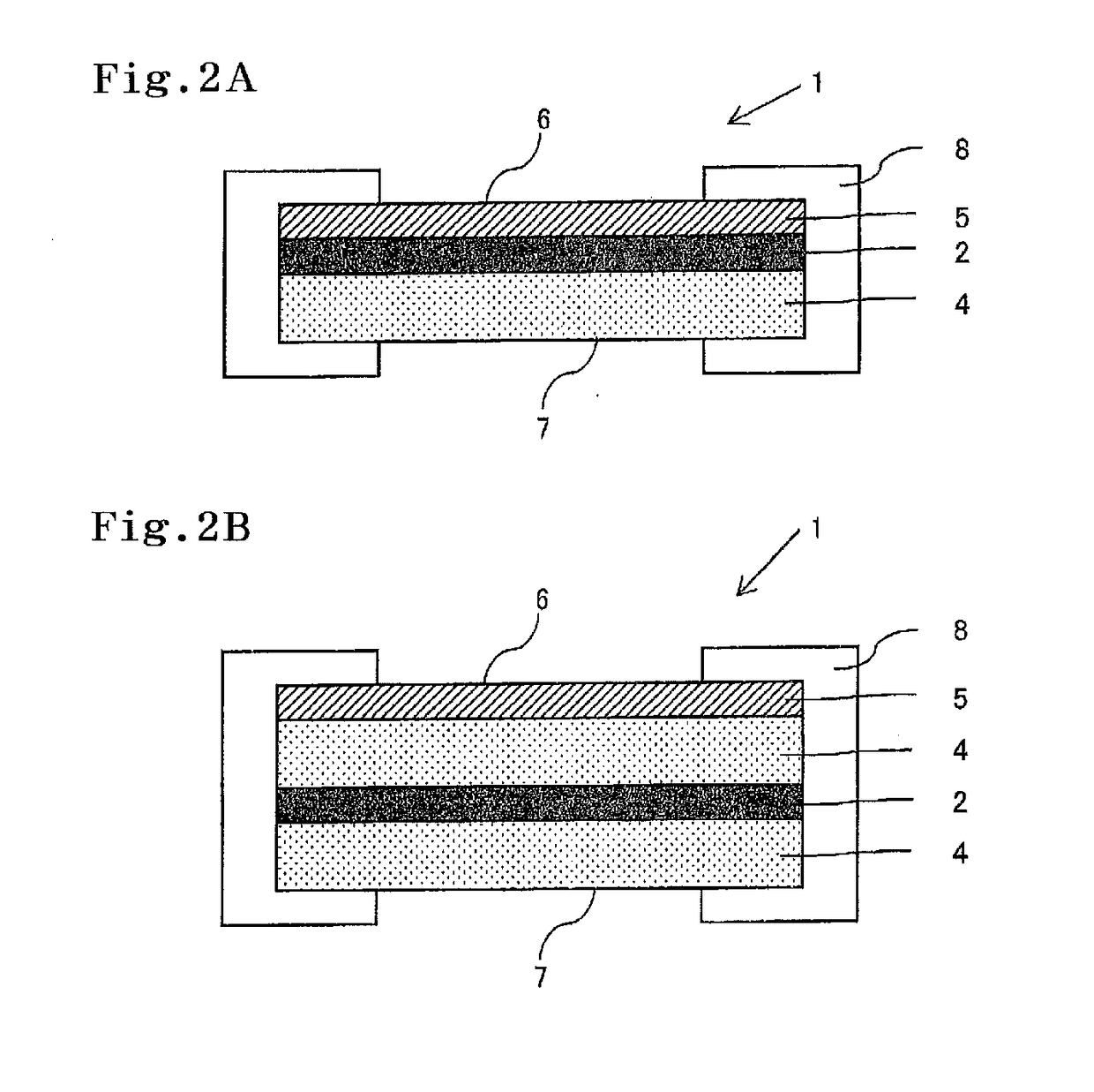
Image

Examples
production example 1
[Preparation of Pd—Au Alloy Layer by Rolling Method (Content of Au: 30 mol %)]
[0073]The raw materials Pd and Au were each weighed so that the content of Au in an ingot became 30 mol %, charged into an arc melting furnace equipped with a water-cooled copper crucible and subjected to arc melting in an Ar gas atmosphere under atmospheric pressure. The obtained button ingot was cold-rolled to a thickness of 5 mm using a two-stage rolling mill having a diameter of 100 mm to obtain a rolled sheet material. Then the rolled sheet material was placed in a glass tube and the both ends of the glass tube were sealed. After reducing the inside pressure of the glass tube to 5×10⁻⁴ Pa at room temperature, the temperature was then raised to 700° C. and the glass tube was allowed to stand for 24 hours, followed by cooling to room temperature. By this heat treatment, the segregation of Pd and Au in the alloy was removed. Then, the sheet material was cold-rolled to 100 μm using a two-stage rolling mil...
production example 2
[Preparation of Pd—Ag Alloy Layer by Rolling Method (Content of Ag: 30 Mol %)]
[0074]A Pd—Ag alloy layer having a thickness of 20 μm and an Ag content of 30 mol % was prepared in the same manner as in Production Example 1, except that the raw materials Pd and Ag were respectively used so that the content of Ag in an ingot became 30 mol %.
example 1
[0075]A coat layer raw material composition (DURASURF DS-3302TH, manufactured by Harves Co., Ltd.) was coated by a dip coating method on one side of the Pd—Au alloy layer produced in Production Example 1, and dried to form a coat layer, thereby to prepare a hydrogen-releasing film.
PUM
 Abstract
Description
Claims
Application Information
 - R&D
- Intellectual Property
- Life Sciences
- Materials
- Tech Scout
- Unparalleled Data Quality
- Higher Quality Content
- 60% Fewer Hallucinations
Browse by: Latest US Patents, China's latest patents, Technical Efficacy Thesaurus, Application Domain, Technology Topic, Popular Technical Reports.
© 2025 PatSnap. All rights reserved.Legal|Privacy policy|Modern Slavery Act Transparency Statement|Sitemap|About US| Contact US: help@patsnap.com