Blower

Inactive Publication Date: 2017-09-14
DENSO CORP
View PDF40 Cites 12 Cited by
  • Summary
  • Abstract
  • Description
  • Claims
  • Application Information

AI Technical Summary

Benefits of technology

The present invention relates to a blower that can improve its serration effect. The blower has a configuration where a main flow of air is generated between adjacent blade tips, and the main flow flows along ribs that run from the recessed portions to the rear edges of the blades. This configuration helps to adjust the directions of air flows on the negative pressure surface to be parallel to each other, which prevents collisions between the main flows and maintains them in close proximity to the negative pressure surface. The recessed portions also have an increased number of ribs to further improve the serration effect by adjusting the directions of air flows on the positive pressure surface to also be parallel to each other. This results in stable air flows from the rear edge and improves the overall performance of the blower.

Problems solved by technology

However, as a result of a test of the effects of the foregoing serration, which was actually conducted by the inventors of the present disclosure, it was found that expected effects could not be acquired fully for the reasons described below.
Therefore, main flows, which respectively involve downward flows generated by the serration, collide with each other on the negative pressure surface, and thereby turbulence of air flows occurs.
As a result, a suppressing effect that prevents the main flows from separating from the negative pressure surface is not fully exerted.
Such a disadvantage occurs not only in an axial blower but also in other blowers in which the blades are serrated, such as a centrifugal fan and a cross-flow fan.

Method used


Image

  • Blower
  • Blower
  • Blower

Examples


first embodiment

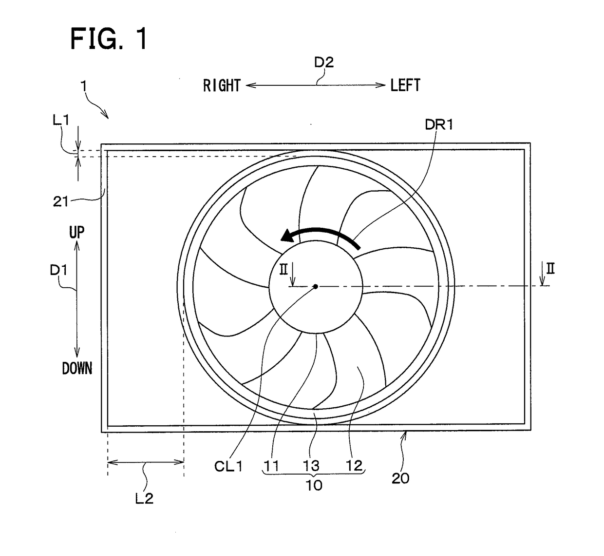
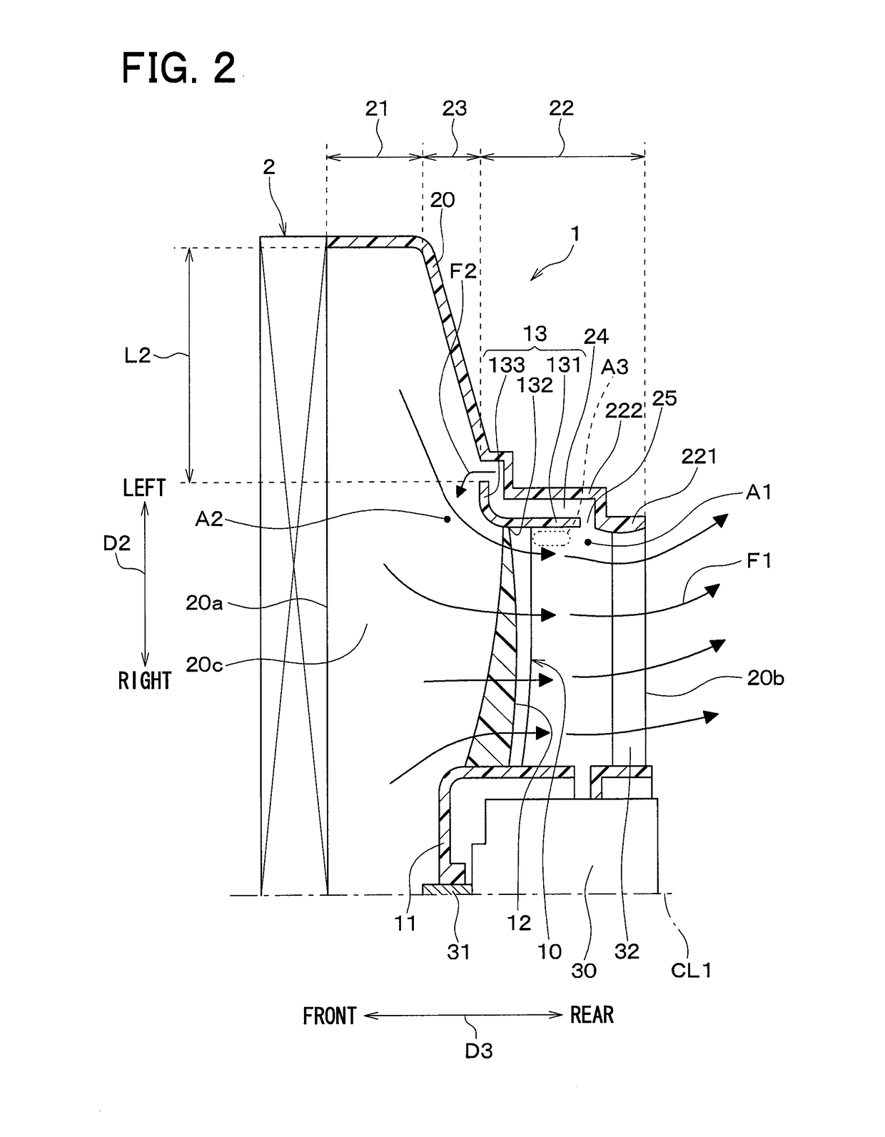
[0034]In the present embodiment, a description will be given using an example where a blower according to the present disclosure is applied to an axial blower 1 that blows air in an axial direction. First, referring to FIGS. 1, 2, the overall configuration of the axial blower 1 according to the present embodiment will be described. FIG. 1 is a front view of the axial blower 1 viewed from the upstream of air flow. In FIGS. 1, 2, a double-headed arrow D1 indicating an up-down direction, a double-headed arrow D2 indicating a left-right direction, and a double-headed arrow D3 indicating a front-rear direction are viewed when the axial blower 1 is mounted in a vehicle.

[0035]The axial blower 1 according to the present embodiment is a blower for a vehicle. Specifically, the axial blower 1 is mounted in a radiator 2 for a vehicle and supplies air to the radiator 2. The radiator 2 is a heat exchanger that cools coolant water through heat exchange between air and coolant water for an engine u...

second embodiment

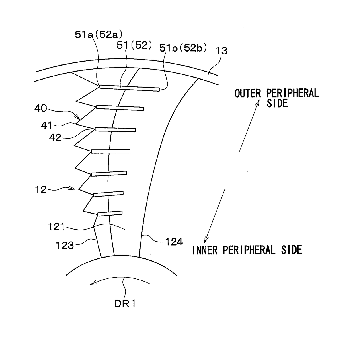
[0075]The quantity of the ribs 51 in the present embodiment is smaller than in the first embodiment, but the other configurations in the present embodiment are identical to those in the first embodiment.

[0076]As shown in FIG. 9, in the present embodiment, ribs 51 are provided only for every other recessed portion 42 of recessed portions 42 of the serration 40. As just described, according to the present embodiment, a quantity of the recessed portions 42 and a quantity of the ribs 51 are not equal to each other such that the quantity of the ribs 51 is smaller than the quantity of recessed portions 42.

[0077]Even if the quantity of the ribs 51 is smaller than the quantity of recessed portions 42 as in the present embodiment, the effect of restricting separation of main flows F4 on the negative pressure surfaces 121, which is caused by downward flows F5 created by the serration 40, can be exhibited fully, compared to a case where ribs 51 are not provided on the negative pressure surface...

third embodiment

[0080]As with the second embodiment, the quantity of the ribs 51 in the present embodiment is smaller than that in the first embodiment. In addition, the quantity of the ribs 51 on the outer peripheral portion of the serration 40 is larger than the quantity of the ribs 51 on the outer peripheral portion of the serration 40. Other configurations in the present embodiment are identical to those in the first embodiment.

[0081]As shown in FIG. 10, in the present embodiment, ribs 51 are provided in recessed portions 42 located in the first to fifth positions from the outer peripheral side, other than recessed portions 42 located in the first and second positions from the inner peripheral side.

[0082]Here, the inner-peripheral-side portion of an axial fan 10 from the position of the radial center of the axial fan 10 in the area in which the serration 40 is formed is referred to as an inner peripheral portion of the serration 40. The outer-peripheral-side portion of the axial fan 10 from the...


PUM


Abstract

A blower includes a fan that has blades and generates an air flow by rotating. Each of the blades has a front edge and a serration provided at least in a part of the front edge. The serration has tip portions and recessed portions arranged alternately with each other. Each of the blades has a negative pressure surface and one or more ribs protruding from the negative pressure surface. Each of the ribs extends from a corresponding one of the recessed portions, which is designated as a starting point, toward a rear edge of a corresponding one of the blades.

Description

CROSS REFERENCE TO RELATED APPLICATIONS[0001]This application is based on Japanese Patent Application No. 2014-190016 filed on Sep. 18, 2014 and Japanese Patent Application No. 2015-083573 filed on Apr. 15, 2015, the disclosures of which are incorporated herein by reference.TECHNICAL FIELD[0002]The present disclosure relates to a blower.BACKGROUND ART[0003]A conventional axial blower includes blades, and each of the blades has a front edge provided with a serration (see Patent Literatures 1, 2, for example). A rounding flow of air flowing from an oblique portion of the serration to a negative pressure surface of each of the blades is caused due to the serration when an air flow flows to the front edge of each of the blades. The rounding flow is a downward flow flowing downward toward the negative pressure surface. The downward flow presses a main flow, which flows on the negative pressure surface of each blade from a tip portion of the serration toward the rear edge of the blade, ag...

Claims


Application Information

Patent Timeline
IPC IPC(8): F04D29/38F04D29/32F04D19/00
CPCF04D29/384F04D29/325F04D19/002F04D29/681F04D29/666F05D2240/303
Inventor KOMURA, MASATOYOSHIDA, KENJI
Owner DENSO CORP
Why Eureka
Try Eureka