
Power conversion apparatus

a power conversion and power technology, applied in the direction of electric generator control, dynamo-electric converter control, dynamo-electric gear control, etc., can solve problems such as noise and vibration, and achieve the effect of suppressing the noise and vibration caused by hunting and reducing the distortion of the inter-line voltag

Active Publication Date: 2017-12-21
DENSO CORP
View PDF4 Cites 10 Cited by
  • Summary
  • Abstract
  • Description
  • Claims
  • Application Information

AI Technical Summary

Benefits of technology

The patent is about a power conversion apparatus that aims to reduce noise and vibration caused by the switching of control. The apparatus uses a method to select the first and second fixed value based on the difference between phase voltage command values. This prevents distortion in inter-line voltage due to dead time and suppresses hunting that occurs before and after the switching. As a result, noise and vibration caused by hunting can be suppressed.

Problems solved by technology

In cases in which driving is performed while the modulation process is switched between the two-phase modulation and the three-phase modulation as in JP-A-2012-125022, hunting may occur before and after the switching, thereby causing noise and vibration.

Method used


Image

  • Power conversion apparatus
  • Power conversion apparatus
  • Power conversion apparatus

Examples


first embodiment

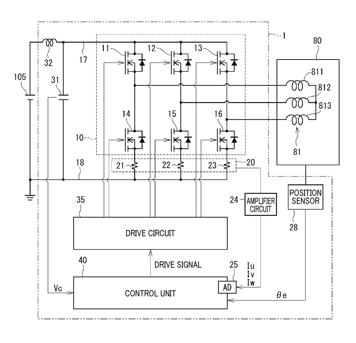
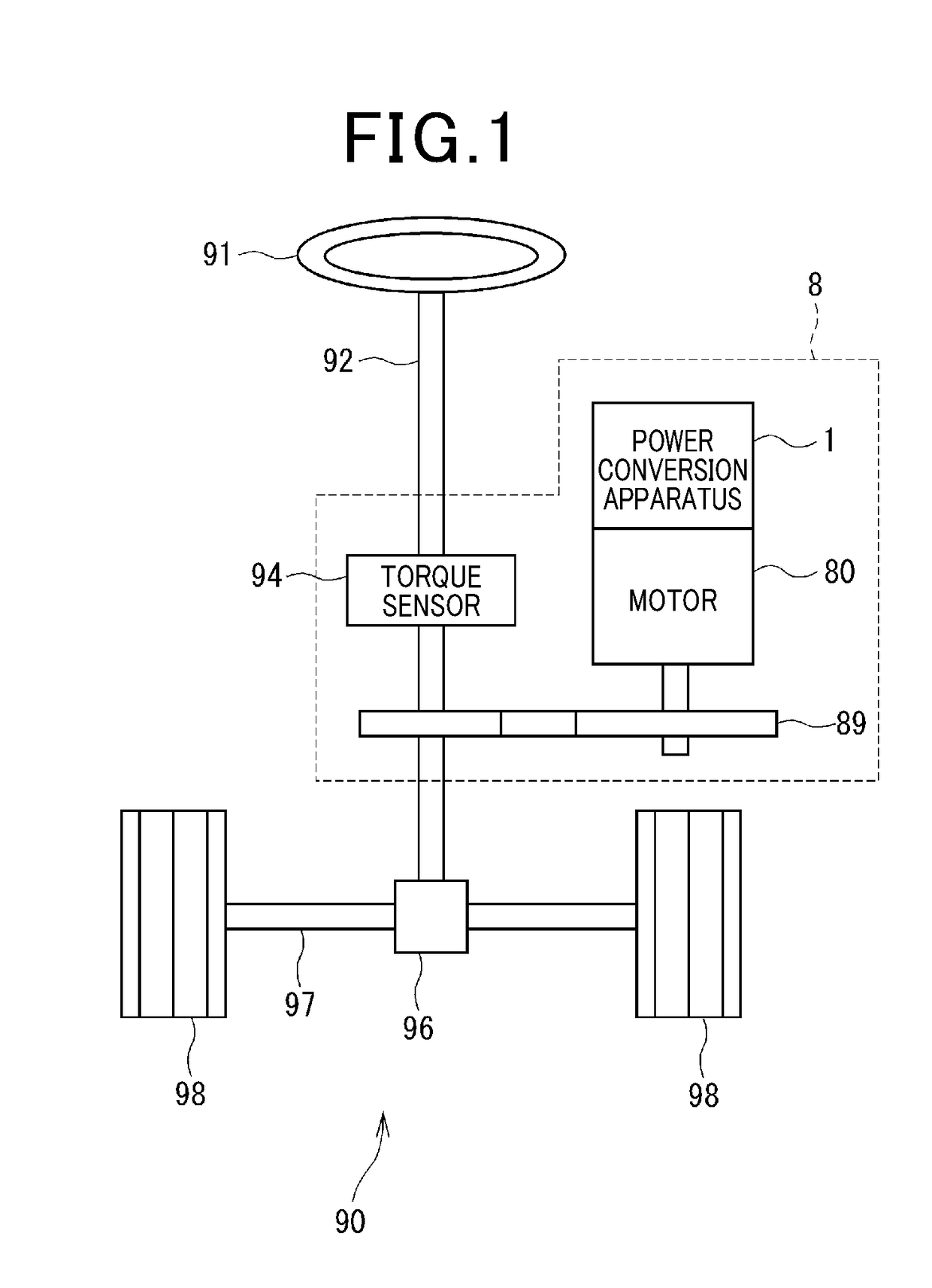
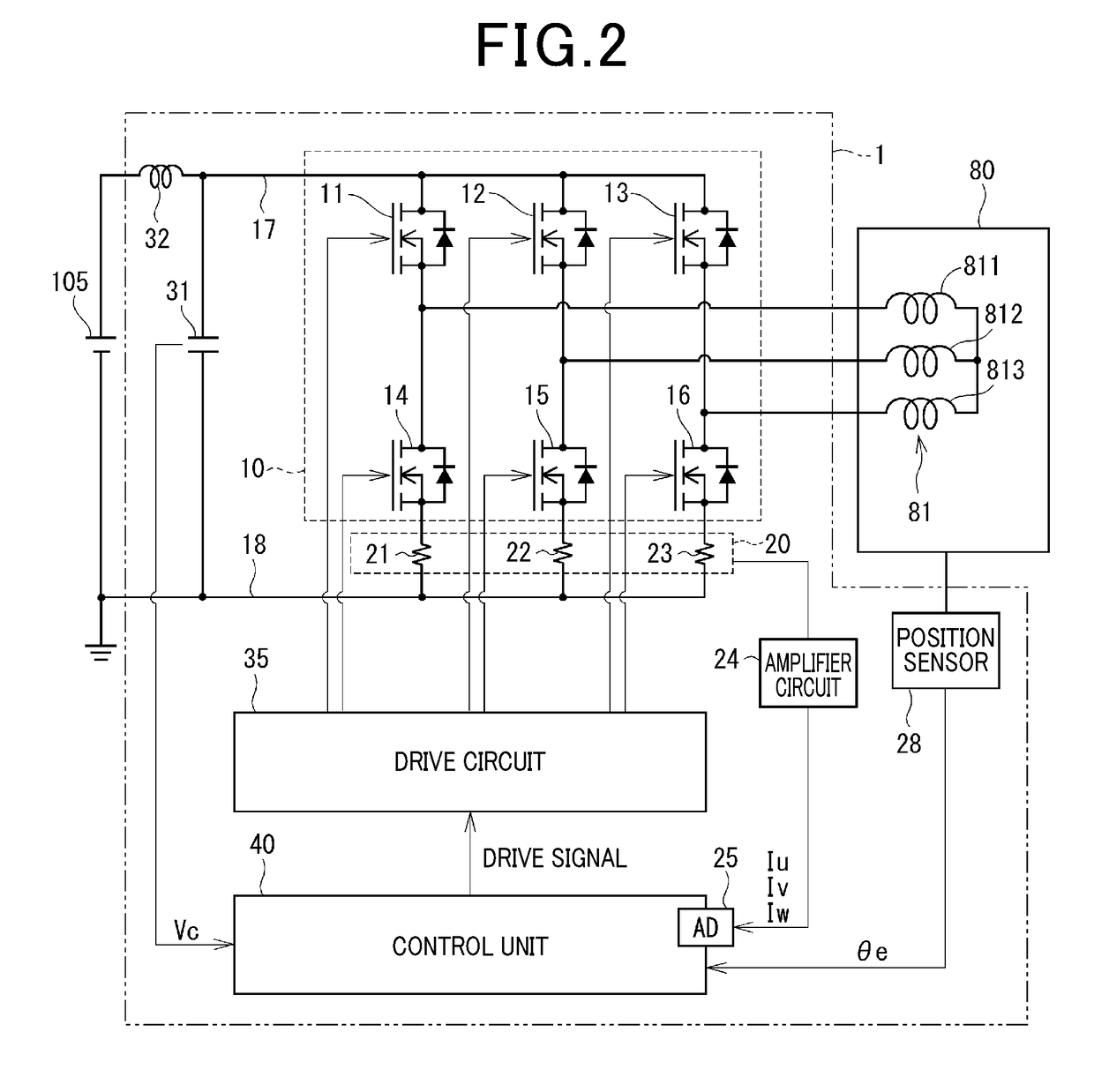
[0025]A first embodiment of the present disclosure will be described with reference to FIGS. 1 to 7C.

[0026]As shown in FIG. 1, a power conversion apparatus 1 is applied to an electric power steering apparatus 8, together with a motor 80. The motor 80 is a rotating electric machine. The electric power steering apparatus 8 assists with steering operations performed by a driver.

[0027]FIG. 1 shows a configuration of a steering system 90 that includes the electric power steering apparatus 8. The steering system 90 includes a steering wheel 91, a steering shaft 92, a pinion gear 96, a rack shaft 97, wheels 98, the electric power steering apparatus 8, and the like. The steering wheel 91 is a steering component.

[0028]The steering wheel 91 is connected to the steering shaft 92. The steering shaft 92 is provided with a torque sensor 94. The torque sensor 94 detects a steering torque Ts that is inputted as a result of the steering wheel 91 being operated by the driver.

[0029]The pinion gear 96 ...

second embodiment

[0100]A second embodiment of the present disclosure is shown in FIG. 8.

[0101]The present embodiment differs from the first embodiment in terms of the process performed by the modulation processing unit 463. Therefore, this difference will mainly be described.

[0102]According to the present embodiment, the modulation processing unit 463 performs Wan up-shift process in which the neutral-point voltage is shifted towards the high voltage side by the largest duty of the phases being modulated to be an upper fixed value Hfix. According to the present embodiment, the up-shift process corresponds to the “modulation process.” Hereafter, the modulation performed such that the largest duty of the phases becomes the upper fixed value Hfix is referred to as “upper flatbed modulation”.

[0103]The modulation processing unit 463 switches the upper fixed value Hfix to a first upper limit value DH1 or a second upper limit value DH2 based on a difference between the input duties Du2, Dv2, and Dw2. Accor...


PUM


Abstract

A modulation processing unit performs a down-shift process or an up-shift process. In the down-shift process, a neutral-point voltage is shifted towards a low voltage side such that a smallest phase voltage command value is a lower fixed value that is a first lower limit value or a second lower limit value. In the up-shift process, the neutral-point voltage is shifted towards a high voltage side such that a largest phase voltage command value is an upper fixed value that is a first upper limit value or a second upper limit value. The modulation processing unit selects either of a first fixed value, being the first lower limit value or the first upper limit value, and a second fixed value, being the second lower limit value or the second upper limit value, based on a difference between the phase voltage command values in the down-shift process or the up-shift process.

Description

CROSS-REFERENCE TO RELATED APPLICATION[0001]This application is based on and claims the benefit of priority from Japanese Patent Application No. 2016-120649, filed Jun. 17, 2016. The entire disclosure of the above application is incorporated herein by reference.BACKGROUNDTechnical Field[0002]The present disclosure relates to a power conversion apparatus.Related Art[0003]Conventionally, a power conversion apparatus that performs a modulation process to improve a voltage utilization rate is known. For example, in JP-A-2012-125022, a power conversion apparatus switches between two-phase modulation and three-phase modulation to prevent a duty at which distortion occurs in an inter-line voltage due to the effects of dead time.[0004]In cases in which driving is performed while the modulation process is switched between the two-phase modulation and the three-phase modulation as in JP-A-2012-125022, hunting may occur before and after the switching, thereby causing noise and vibration.SUMMAR...

Claims


Application Information

Patent Timeline
Patent Type & Authority Applications(United States)
IPC IPC(8): H02M7/487H02P21/22H02M7/5395H02P21/00H02P6/16B62D5/04
CPCH02M7/487H02P6/16H02M7/5395B60Y2400/61H02P21/0003B62D5/0412H02P21/22H02P27/08
Inventor SUZUKI
Owner DENSO CORP
Learn More