
Battery-equipped device

a battery and battery technology, applied in the direction of batteries, sustainable manufacturing/processing, cell components, etc., can solve the problems of not getting the expected increase in capacity and energy density, and achieve the effect of improving capacity, capacity and energy density, and increasing capacity and energy density

Active Publication Date: 2017-08-10
NGK INSULATORS LTD
View PDF6 Cites 3 Cited by
  • Summary
  • Abstract
  • Description
  • Claims
  • Application Information

AI Technical Summary

Benefits of technology

This patent is about a new type of battery that uses solid state electrolytes, which can improve energy density and capacity. However, the problem with current solid state batteries is that they cannot achieve maximum efficiency with thick positive electrode layers. The inventors have discovered that by using oriented positive electrode plates made of polycrystalline materials, the batteries can have increased capacity and energy density. Additionally, this new battery design can conform to the shape of a device, allowing for more flexibility in design and minimal space requirement. The technical effects of this patent text are improved battery performance and increased design flexibility for battery-equipped devices.

Problems solved by technology

All-solid-state batteries including non-oriented positive-electrode active materials as shown in Patent Documents 1 and 2 have a problem in that the expected increases in the capacity and energy density are not obtained even if a thick positive electrode layer is formed.

Method used


Image

  • Battery-equipped device
  • Battery-equipped device
  • Battery-equipped device

Examples


example 1

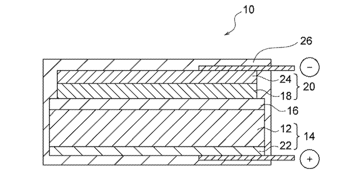
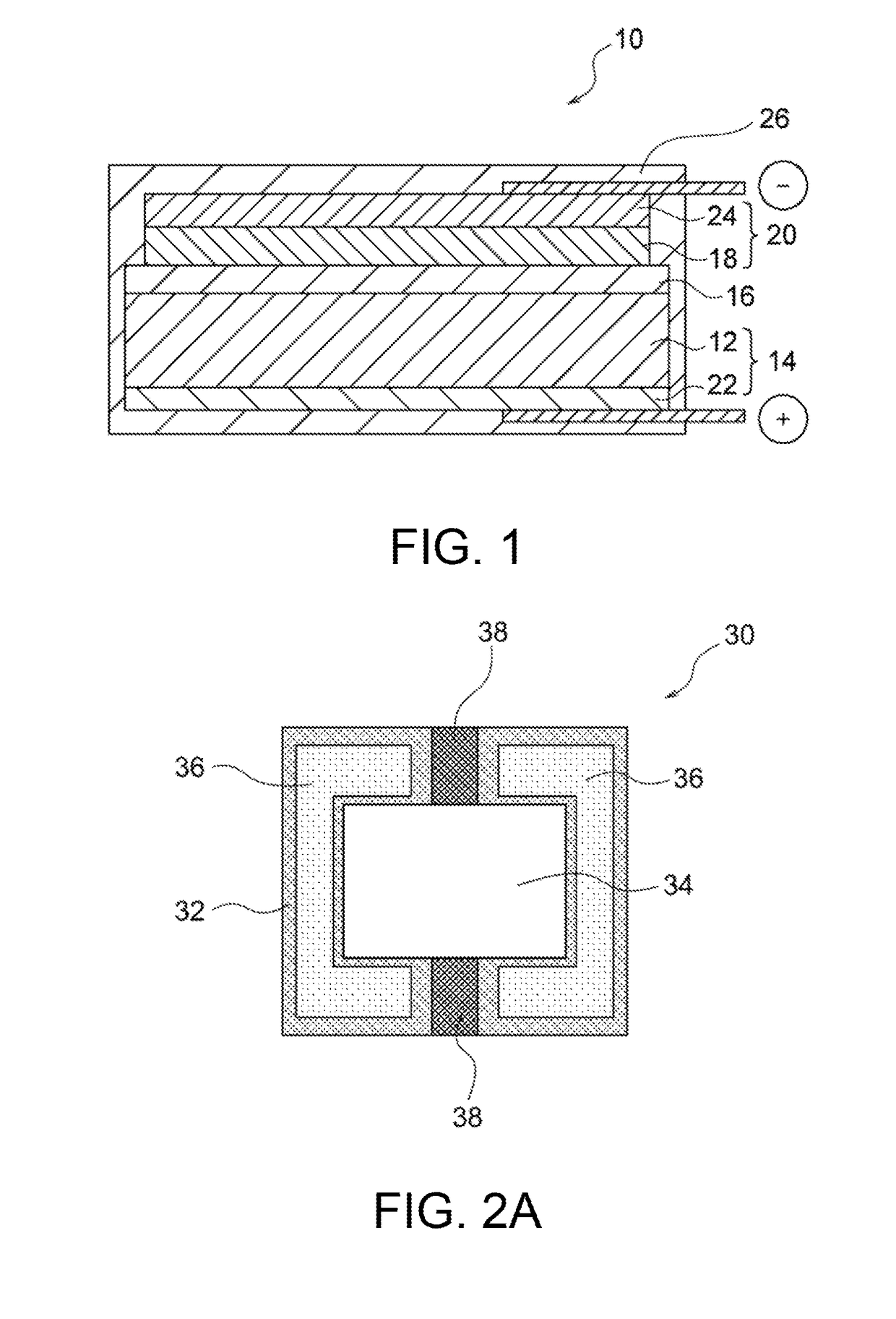
[0106]An all-solid-state battery 10 having the configuration in FIG. 1 was produced. A positive-electrode active material sheet was produced as a positive-electrode active material 12 that had a layered rock-salt structure, a composition Li(Ni1 / 3Co1 / 3Mn1 / 3)O2 (hereinafter referred to as NCM), and the (003) plane oriented in the direction from a positive electrode layer 14 toward a negative electrode layer 20. A positive-electrode active material sheet having a thickness of 30 μm was prepared. A solid electrolyte layer 16 was formed on the sheet positive-electrode active material 12. A ceramic material having a garnet-type crystal structure having a composition Li7La3Zr2O12 containing Al (hereinafter referred to as LLZ-AI) was used as a lithium-ion conductive material of the solid electrolyte layer 16. The solid electrolyte layer 16 was prepared to have a thickness of 10 μm. A negative-electrode active material 18 having a thickness of 10 μm was prepared with lithium metal. A positiv...

example 2

[0108]The unit cells produced in Example 1 were stacked in parallel to produce a battery having a capacity of 100 mAh. The energy density calculated as in Example 1 was 650 Wh / L.

example 3

[0109]The unit cells produced in Example 1 were stacked in parallel to produce a battery having a capacity of 300 mAh. The energy density calculated as in Example 1 was 750 Wh / L.


PUM


Abstract

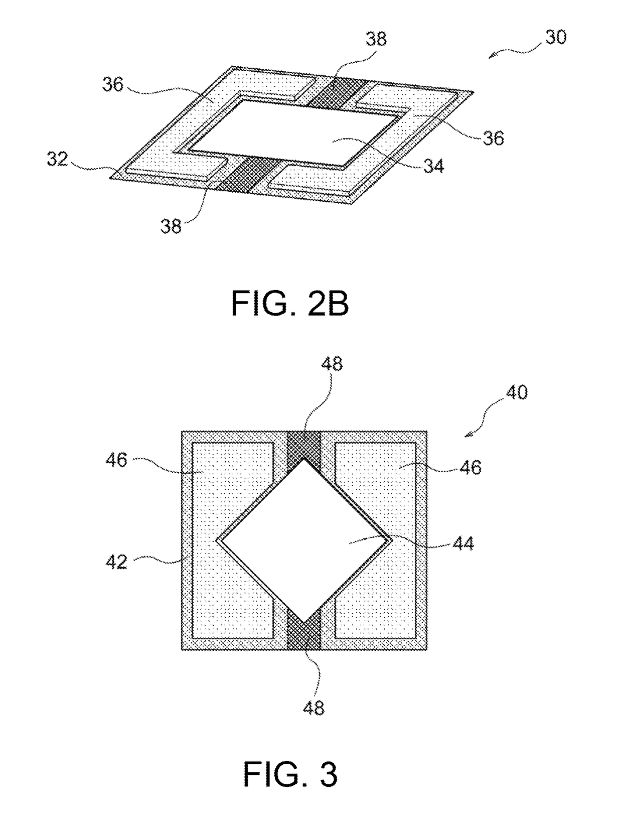
Provided is a battery-equipped device including a substrate, a device disposed on the substrate, an all-solid-state battery disposed such that the planar shape conforms to the periphery of the device on the substrate and at least partially having a complementary outer edge shape that conforms to the entire or a part of the outer edge shape of the device, and interconnections connecting the device and the all-solid-state battery. The all-solid-state battery includes a positive electrode layer containing an oriented polycrystalline positive-electrode active material composed of lithium transition metal oxide particles oriented in a certain direction, a solid electrolyte layer composed of a lithium-ion conductive material, and a negative electrode layer containing a negative-electrode active material. The present invention can provide a battery-equipped device that can significantly increase the degree of freedom of design and can output necessary electric power in a minimum space.

Description

CROSS-REFERENCE TO RELATED APPLICATIONS[0001]This application is a continuation application of PCT / JP2015 / 068416 filed Jun. 25, 2015, which claims priority to Japanese Patent Application No. 2014-249371 filed Dec. 9, 2014, the entire contents all of which are incorporated herein by reference.BACKGROUND OF THE INVENTION[0002]1. Field of the Invention[0003]The present invention relates to a battery-equipped device.[0004]2. Description of the Related Art[0005]The recent development of portable devices, such as personal computers and cellular phones, has been greatly expanding the demand for batteries as the power sources of the devices. Traditional batteries for such application contain liquid electrolytes (electrolytic solutions) containing flammable organic diluent solvents, as media for ion transfer. The battery containing such an electrolytic solution has a risk of the leakage of the electrolytic solution, ignition, explosion, or the like.[0006]To solve the problems, an all-solid-s...

Claims


Application Information

Patent Timeline
IPC IPC(8): H01M10/0562H01M4/525H01M10/0525H01M4/505H01M4/38H01M10/0585H01M50/209
CPCH01M10/0562H01M4/382H01M10/0585H01M2220/30H01M4/505H01M4/525H01M2300/0071H01M10/0525H01M10/052H01M2300/0068Y02E60/10H01M50/209Y02P70/50
Inventor OHWADA, IWAOYOSHIDA, TOSHIHIROKITOH, KENSHIN
Owner NGK INSULATORS LTD
Learn More