
Cutting elements and methods for fabricating diamond compacts and cutting elements with functionalized nanoparticles

a technology of cutting elements and nanoparticles, applied in the direction of manufacturing tools, grinding/polishing apparatus, grinding devices, etc., can solve the problems of diamond table delaminate from the substrate, diamond table thermal damage, and relatively large compressive and tensile stresses

Active Publication Date: 2017-07-27
BAKER HUGHES INC
View PDF8 Cites 2 Cited by
  • Summary
  • Abstract
  • Description
  • Claims
  • Application Information

AI Technical Summary

Benefits of technology

This patent describes a method of making a cutting tool for drilling through the earth. The process involves coating diamond nanoparticles with fluorine, mixing them with a non-group-VIII metal, and applying high pressure and high temperature conditions to create strong bonds between the nanoparticles and the surrounding material. This results in a cutting tool with superior strength and performance.

Problems solved by technology

The presence of the catalyst material in the diamond table may contribute to thermal damage in the diamond table when the cutting element is heated during use, due to friction at the contact point between the cutting element and the formation.
This differential in thermal expansion rates may result in relatively large compressive and tensile stresses at the interface between the diamond table and the substrate, and may cause the diamond table to delaminate from the substrate.
For example, cobalt thermally expands significantly faster than diamond, which may cause cracks to form and propagate within a diamond table including cobalt, eventually leading to deterioration of the diamond table and ineffectiveness of the cutting element.
Thermally stable polycrystalline diamond cutting elements in which substantially all catalyst material has been leached from the diamond table have been reported to be thermally stable up to temperatures of about 1,200° C. It has also been reported, however, that fully leached diamond tables are relatively more brittle and vulnerable to shear, compressive, and tensile stresses than are non-leached diamond tables.

Method used


Image

  • Cutting elements and methods for fabricating diamond compacts and cutting elements with functionalized nanoparticles
  • Cutting elements and methods for fabricating diamond compacts and cutting elements with functionalized nanoparticles
  • Cutting elements and methods for fabricating diamond compacts and cutting elements with functionalized nanoparticles

Examples


example 1

ering of Non-Fluorinated Crushed Nanodiamond

[0049]A sample of crushed nanodiamond (i.e., diamond nanoparticles) having a mean particle diameter of 90 nm was obtained from NanoDiamond Products, Ltd., of Shannon, Ireland. The crushed nanodiamond was mechanically mixed (i.e., as dry powders) with submicron aluminum powder having a mean particle diameter of 800 nm, which was obtained from US Research Nanomaterials, Inc., of Houston, Tex. The mixture was approximately 85% crushed nanodiamond and 15% aluminum. The crushed nanodiamond and aluminum were subjected to HPHT sintering at a maximum pressure of 8.0 GPa and a maximum temperature of about 1,600° C., for about 20 seconds. The microstructure of the polycrystalline diamond material was photographed by SEM, and is depicted in FIG. 7.

example 2

ering of Fluorinated Crushed Nanodiamond

[0050]A sample of crushed nanodiamond having a mean particle diameter of 90 nm was obtained from NanoDiamond Products, Ltd. The crushed nanodiamond was coated with fluorine to form covalent C—F bonds on surfaces of the nanodiamond by exposing the crushed nanodiamond to fluorine gas (F2) at a temperature of 340° C. for 300 minutes. The crushed nanodiamond was mechanically mixed (i.e., as dry powders) with submicron aluminum powder having a mean particle diameter of 800 nm, which was obtained from US Research Nanomaterials, Inc. The mixture was approximately 85% fluorinated crushed nanodiamond and 15% aluminum. The fluorinated crushed nanodiamond and aluminum were subjected to HPHT sintering at a maximum pressure of 8.0 GPa and a maximum temperature of about 1,600° C., for about 20 seconds. The microstructure of the polycrystalline diamond material was photographed by SEM, and is depicted in FIG. 8.

[0051]A comparison of the SEM images of FIGS. 7...

example 3

ering of Fluorinated Crushed Nanodiamond for 30 Seconds

[0052]Two samples of fluorinated crushed nanodiamond and aluminum were prepared as in Example 2. The samples were sintered together at a maximum pressure of 8.0 GPa and a maximum temperature of about 1,600° C., for about 30 seconds. The samples were tested by X-ray diffraction (XRD) to determine chemical composition, with the resulting XRD spectrum shown in FIG. 9. The peak at 2Θ=25 indicates that each of the sintered samples contained aluminum fluoride (AlF3). No aluminum carbide (Al4C3) was detected in these samples. The diamond peaks are narrow, indicating that the particles of diamond had uniform, near-perfect crystalline structure.

[0053]In the middle of the samples, the color of the material at the cleavage point appeared white, and included particles having micron sizes. At the ends of the sample (portions that experienced lower maximum temperatures than the middle), bright spherical zones of growth and enlargement of nano...


PUM

PropertyMeasurementUnit
pressureaaaaaaaaaa
temperatureaaaaaaaaaa
diameteraaaaaaaaaa

Abstract

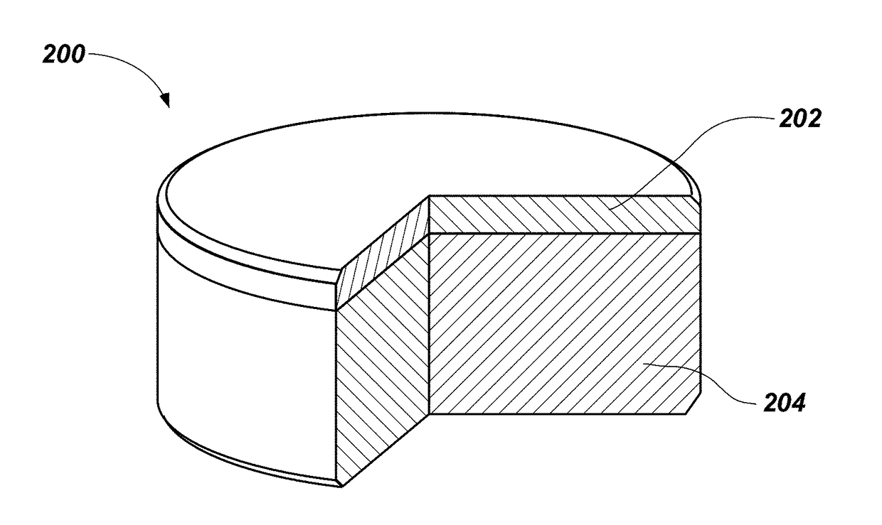
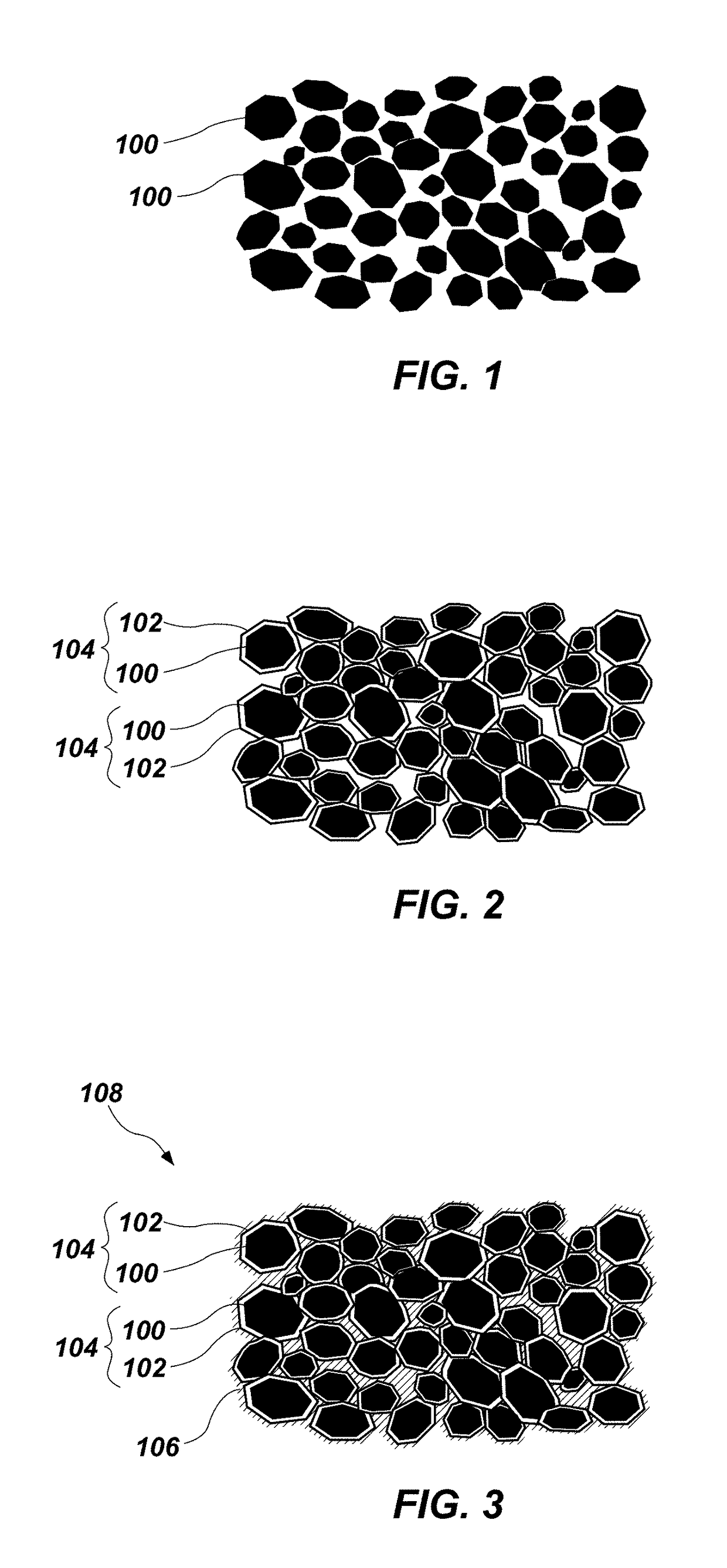
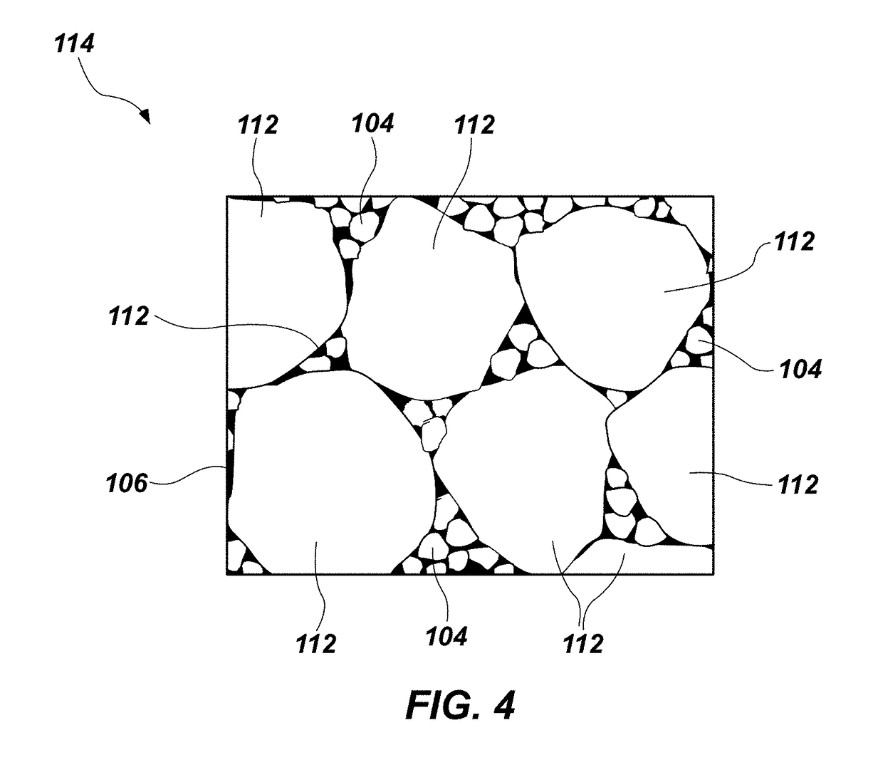
A method of fabricating a diamond compact includes functionalizing surfaces of diamond nanoparticles with fluorine; combining the functionalized diamond nanoparticles with a non-group-VIII metal to form a particle mixture; and subjecting the particle mixture to high pressure and high temperature (HPHT) conditions to form inter-granular bonds between the diamond nanoparticles. A cutting element for an earth-boring tool includes a plurality of grains of diamond material; a plurality of diamond nanoparticles bonded to the plurality of grains of diamond material; and a non-group-VIII metal fluoride disposed within interstitial spaces between the grains of diamond material and the plurality of diamond nanoparticles. The cutting element is substantially free of a metal-solvent catalyst.

Description

FIELD[0001]Embodiments of the present disclosure relate generally to methods of forming polycrystalline diamond material, cutting elements and methods of forming cutting elements including polycrystalline diamond material, and green bodies that may be used to form such cutting elements.BACKGROUND[0002]Earth-boring tools for forming wellbores in subterranean earth formations may include a plurality of cutting elements secured to a body. For example, fixed-cutter earth-boring rotary drill bits (also referred to as “drag bits”) include a plurality of cutting elements fixedly attached to a bit body of the drill bit. Similarly, roller cone earth-boring rotary drill bits include cones mounted on bearing pins extending from legs of a bit body such that each cone is capable of rotating about the bearing pin on which the cone is mounted. A plurality of cutting elements may be mounted to each cone of the drill bit.[0003]The cutting elements used in such earth-boring tools often include polycr...

Claims


Application Information

Patent Timeline
Patent Type & Authority Applications(United States)
IPC IPC(8): B24D18/00C04B35/645C04B35/52C04B35/626E21B10/46B24D3/06
CPCC04B2235/66B24D18/0009E21B10/46B24D3/06C04B35/52C04B2235/402C04B35/645Y10S977/773B82Y30/00C04B2235/427C04B35/62685C04B35/528C04B35/62802C04B35/62884C04B35/6303C04B2235/40C04B2235/401C04B2235/407C04B2235/408C04B2235/445C04B2235/5436C04B2235/5454C04B2235/5472C04B2235/80
Inventor KHABASHESKU, VALERY N.FILONENKO, VLADIMIR P.
Owner BAKER HUGHES INC
Learn More