
Nanosensors based on functionalized nanoparticles and Surface Enhanced Raman Scattering

a functionalized nanoparticle and nanosensor technology, applied in the field of molecular sensors and methods of identification, can solve the problems of low raman scattering cross-sections of typical molecular structures, and historically limited application of low sensitivity to highly concentrated samples

Active Publication Date: 2006-03-09
LAWRENCE LIVERMORE NAT SECURITY LLC
View PDF12 Cites 24 Cited by
  • Summary
  • Abstract
  • Description
  • Claims
  • Application Information

AI Technical Summary

Benefits of technology

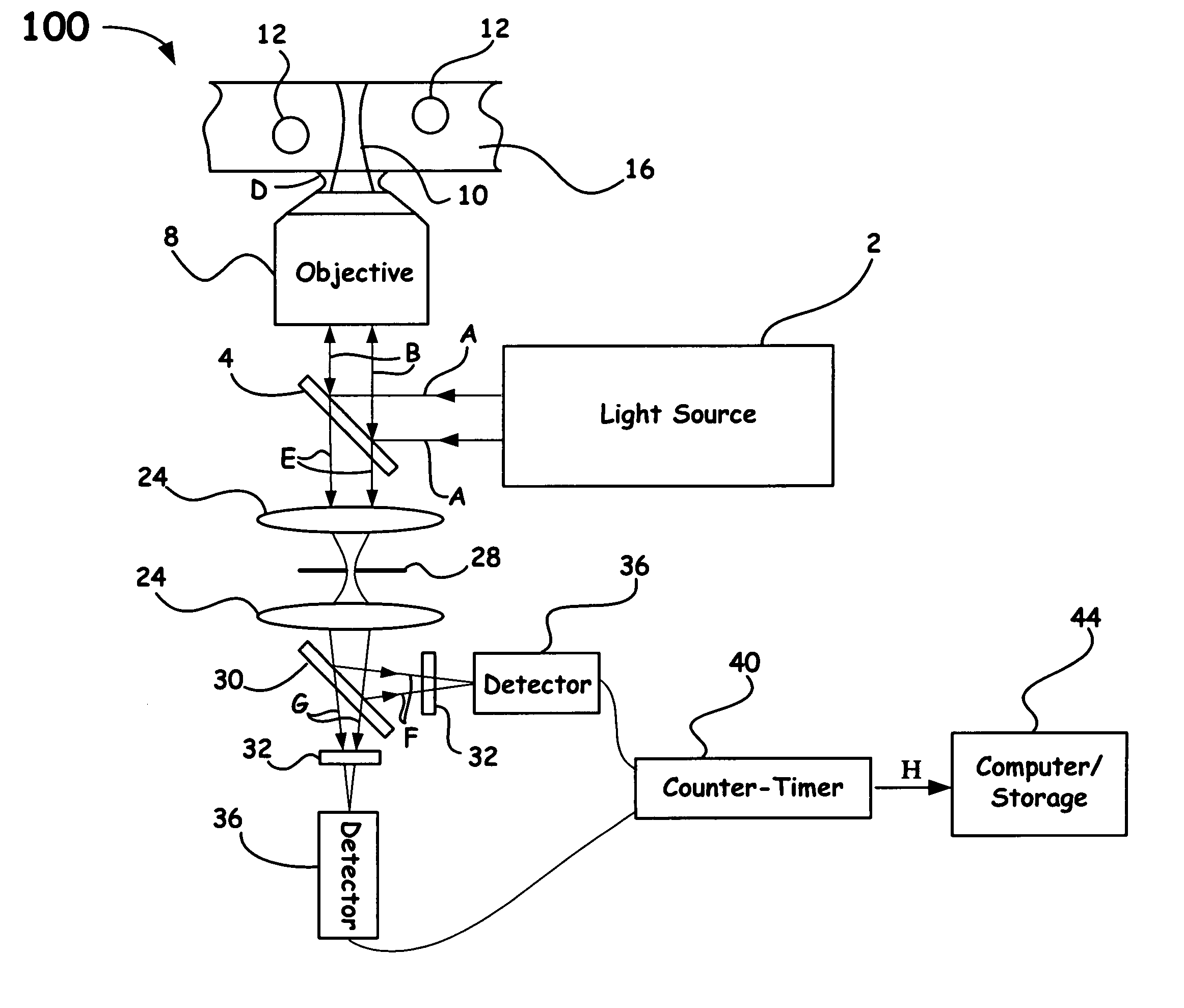
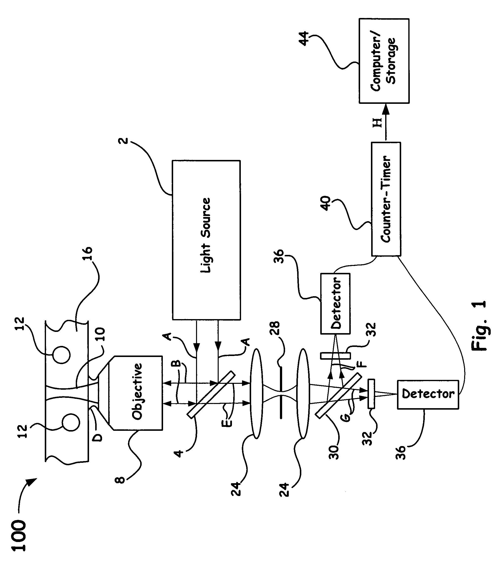
[0014] The present invention is directed to a surface-enhanced Raman spectroscopy (SERS) apparatus that utilizes designed nanosensors and detection means to determine the presence and concentration of one or more target molecules, and/or changing physical and/or chemical conditions of an analyte.
[0015] Another aspect of the present invention is directed to a surface-enhanced Raman spectroscopy (SERS) system having a directed electromagnetic radiation source, one or more nanosensors, optical detectors configured to monitor ratiometric signals of a collected SERS spectra coupled with means to determine the presence and concentration of one or more target molecules, and/or changing physical and/or chemical conditions of an analyte.
[0016] A final aspect of the present invention is directed to a SERS-based detection method that includes providing one or more nanosensors, each having a metal nanoparticle covalen...

Problems solved by technology

A drawback of Raman spectroscopy, however, is that the typical molecular cross-sections for Raman scattering are extremely low, on the order of 10−29 cm−2.
While Raman spectroscopy has been used as an analytical tool for certain applications due to its excellent specificity for chemical group identification, its low sensitivity historically has limited its applications to highly concentrated samples.

Method used


Image

  • Nanosensors based on functionalized nanoparticles and Surface Enhanced Raman Scattering
  • Nanosensors based on functionalized nanoparticles and Surface Enhanced Raman Scattering
  • Nanosensors based on functionalized nanoparticles and Surface Enhanced Raman Scattering

Examples


Embodiment Construction

[0027] Referring now to the following detailed information, and to incorporated materials; a detailed description of the invention, including specific embodiments, is presented.

[0028] Unless otherwise indicated, numbers expressing quantities of ingredients, constituents, reaction conditions and so forth used in the specification and claims are to be understood as being modified by the term “about.” Accordingly, unless indicated to the contrary, the numerical parameters set forth in the specification and attached claims are approximations that may vary depending upon the desired properties sought to be obtained by the subject matter presented herein. At the very least, and not as an attempt to limit the application of the doctrine of equivalents to the scope of the claims, each numerical parameter should at least be construed in light of the number of reported significant digits and by applying ordinary rounding techniques. Notwithstanding that the numerical ranges and parameters se...


PUM


Abstract

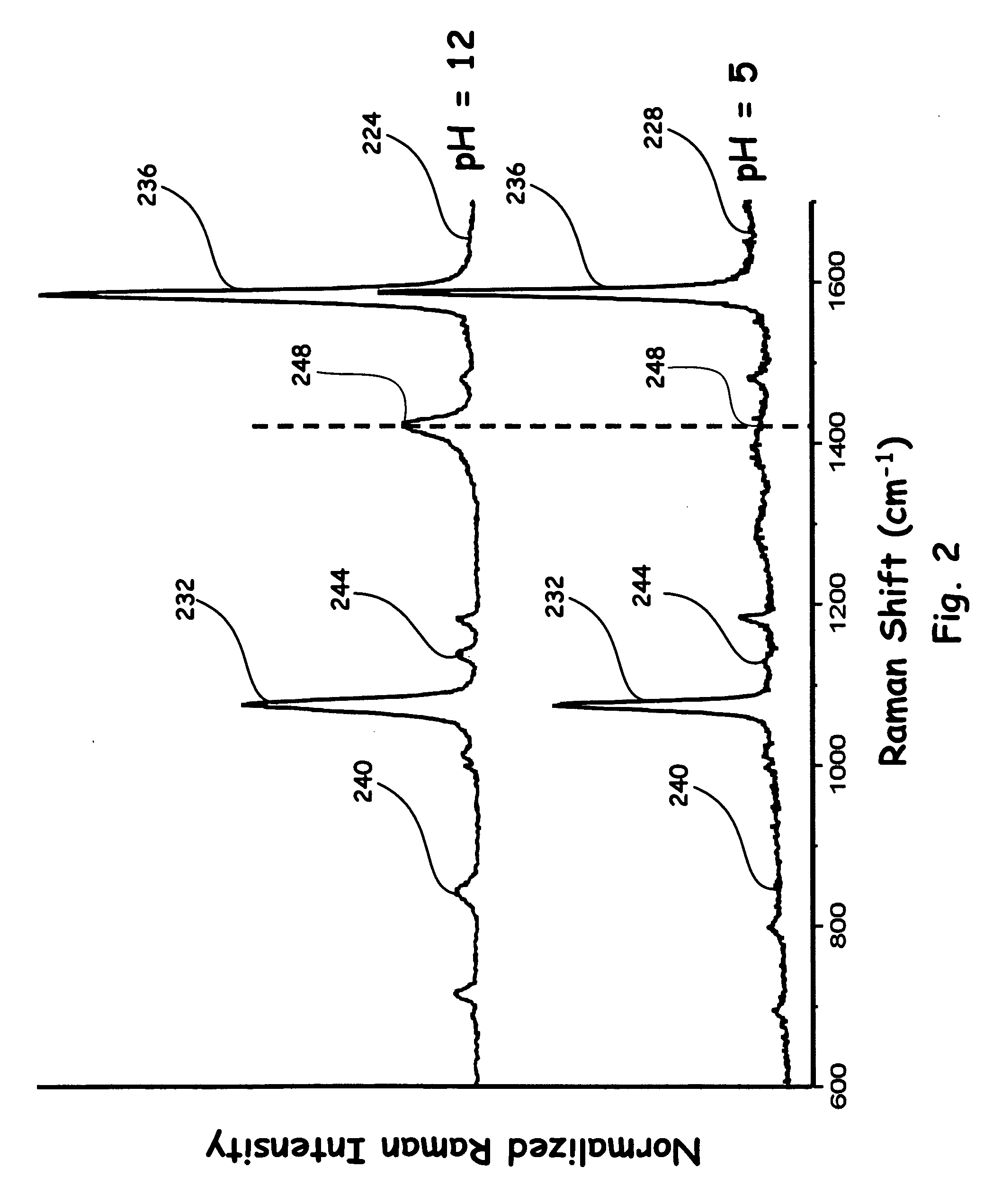
Surface-Enhanced Raman Spectroscopy (SERS) is a vibrational spectroscopic technique that utilizes metal surfaces to provide enhanced signals of several orders of magnitude. When molecules of interest are attached to designed metal nanoparticles, a SERS signal is attainable with single molecule detection limits. This provides an ultrasensitive means of detecting the presence of molecules. By using selective chemistries, metal nanoparticles can be functionalized to provide a unique signal upon analyte binding. Moreover, by using measurement techniques, such as, ratiometric received SERS spectra, such metal nanoparticles can be used to monitor dynamic processes in addition to static binding events. Accordingly, such nanoparticles can be used as nanosensors for a wide range of chemicals in fluid, gaseous and solid form, environmental sensors for pH, ion concentration, temperature, etc., and biological sensors for proteins, DNA, RNA, etc.

Description

[0001] The United States Government has rights in this invention pursuant to Contract No. W-7405-ENG-48 between the United States Department of Energy and the University of California for the operation of Lawrence Livermore National Laboratory.BACKGROUND OF THE INVENTION [0002] 1. Field of the Invention [0003] The present invention relates in general to molecular sensors and methods of identification, and more particularly to a nanosensor detection system for molecular identification based on surface-enhanced Raman scattering (SERS). [0004] 2. Description of Related Art [0005] Raman scattering is the inelastic scattering of optical photons by interaction with vibrational modes of molecules. Typically, Raman scattered photons have energies that are slightly lower (i.e., Stokes-shifted photons) than the incident photons with the energy differences related to molecular vibrational energy levels. The energy spectrum of scattered photons commonly comprise narrow peaks and provides a uniq...

Claims


Application Information

Patent Timeline
IPC IPC(8): G01J3/44
CPCG01N21/658G01J3/44
Inventor TALLEY, CHAD E.HUSER, THOMAS R.HOLLARS, CHRISTOPHER W.LANE, STEPHEN M.SATCHER, JOE H. JR.HART, BRADLEY R.LAURENCE, TED A.
Owner LAWRENCE LIVERMORE NAT SECURITY LLC
Learn More