
Thermal accelerant compositions and methods of use

a technology of thermal accelerant and composition, which is applied in the field of methods, materials and equipment for hyperthermal tissue ablation, can solve problems such as irregularablation, and achieve the effects of complete, complete, and surgically effective ablation of tumor sites

Active Publication Date: 2017-06-29
RHODE ISLAND HOSPITAL +1
View PDF6 Cites 7 Cited by
  • Summary
  • Abstract
  • Description
  • Claims
  • Application Information

AI Technical Summary

Benefits of technology

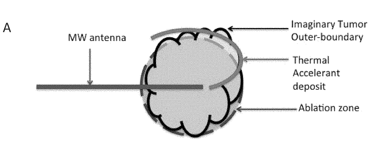
The present invention provides a heat substrate composition or thermal accelerant material that can be used in image-guided thermal ablation to achieve more complete and surgically effective ablation of a tumor. The thermal accelerant is a heat-up quickly when irradiated and can be positioned in various ways to enhance ablation in the tumor area or to promote more uniform and complete ablation despite interfering tissue structures. The use of the thermal accelerant can eliminate the problem of incomplete ablation, which is currently the major contributor to recurrence of a tumor, and that currently limits image-guided thermal ablation to a second-line therapy that is best used for tumors under about 3 cm diameter.

Problems solved by technology

While this short effective range will limit unintended damage to most nearby healthy tissue structures, it also presents a drawback, in that microwave ablation drops off rapidly in only a few centimeters, and the ablation may be irregular due to either the rate of microwave heat generation at the site, or heat conduction away from the site into adjacent tissue, or variations in tissue conductivity and dielectric constant (which may be different for each patient).

Method used


Image

  • Thermal accelerant compositions and methods of use
  • Thermal accelerant compositions and methods of use
  • Thermal accelerant compositions and methods of use

Examples


example 1

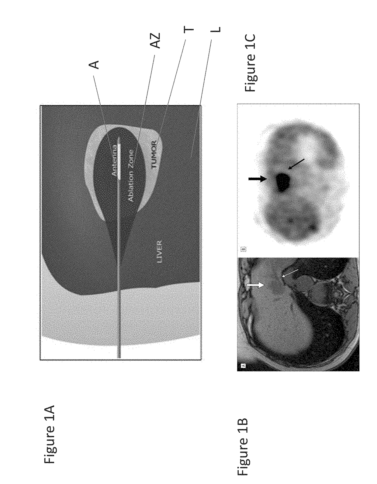
[0035]To mitigate the problem of inadequate heating, applicants devised a novel heat substrate to selectively increase heating and, by suitable placement, avoid undesirable cooling or ‘heat sink’ effects. This substrate is made of cesium chloride (CsCl) and is compounded in a reverse phase transition polymer to be positioned, and then activated by microwave energy from a distance. The reverse phase transition polymer, which may, for example be a PLGA-PEG-PLGA block copolymer of suitable viscosity, transforms into a gel at body temperature or above and with the cesium chloride salt strongly responds to microwave radiation and locally increases the temperature to more effectively ablate tumor cells that lie just outside of ablation zone AZ of FIGS. 1A, 1B and 1C. Furthermore, this heat substrate is an excellent contrast agent by itself, and was found to be visible under CT imaging. These properties make it particularly efficacious for treating solid tumors, where a physician can contr...

example 2

Preliminary Study: Augmentation of Microwave Energy

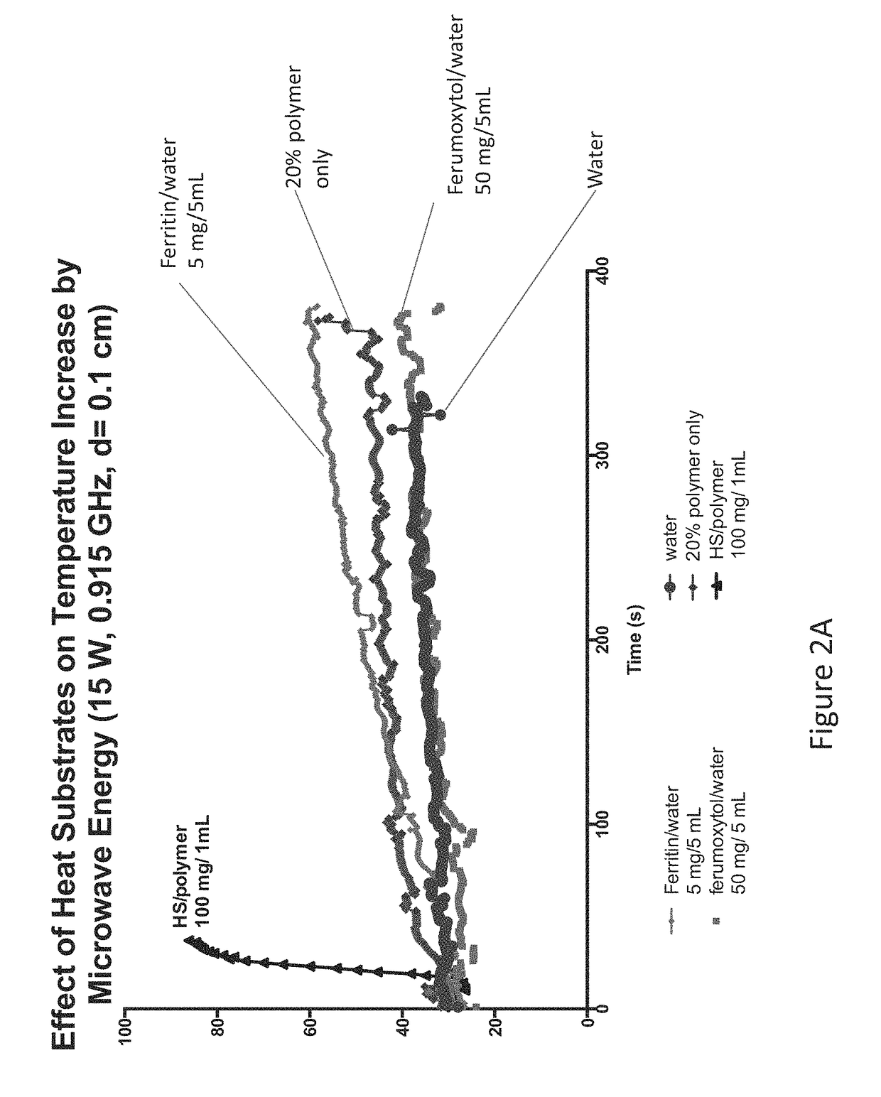
[0048]As a proof of concept, we tested the efficiency of the heat substrate in augmenting the microwave energy. Using a phantom (1% (w / v) agarose medium), temperature increase by a control and the heat substrate (two concentrations: 100 mg / mL and 250 mg / mL, respectively) was measured over time. Under the MW conditions (60 W, 915 MHz, 10 minutes), a maximum ablation zone attained is typically 2.5 cm in diameter (i.e., a zone extending a distance 1.25 cm from the antenna). This distance and the conditions were used as a baseline platform to evaluate the augmentation efficiency of the heat substrate. As depicted in FIG. 6B the heat substrate was placed at 1.5 cm from the antenna, and was heated by MW energy transferred through an MW antenna (MicrothermX® Perseon Medical, Salt Lake City, Utah) to reach tumoricidal temperature (>60° C.). Temperature plots are shown in FIG. 6A. The thermal accelerant was found to augment the MW energy in ...

example 3

[0049]A preliminary study of the thermal accelerant as a CT contrast agent was carried out. Various concentrations of the thermal accelerant (TA) solutions were prepared and measured for their CT contrast. FIG. 2C shows the TA solution with the concentration as low as 10 mg / mL produced a discernable contrast as compared to water. The degree of the CT contrast was found to be proportional to the concentration of the thermal accelerant (TA), so the TA solution is CT visible. The upper portion of FIG. 2C shows four samples 1)-4) as follows: 1. Distilled water −15 Hu, 2. TA (10 mg / mL) 286 Hu, 3. TA (100 mg / mL) 2056 Hu, 4. TA (1000 mg / mL) 3070 Hu. The lower portion of FIG. 2C shows the same samples with computer-aided enhancement. The lowest concentration 10 mg / mL TA yields a discernible contrast compared to water in CT. GE Optima 580 W CT scanner. Used CT protocol: 120 kV, 50 mA, 0.8 second rotation, 0.562:1 pitch, and 16×.625 mm detector configuration. Radiation output (CTDIvol) was 12...


PUM


Abstract

A thermal accelerant is delivered to a tissue site and localized to modulate the shape, extent or other characteristic of RF or microwave-induced hyperthermic tissue ablation. The accelerant may be provided via an image-guided hand piece or via a lumen added to a microwave antenna, and promotes faster heating, more complete ablation and / or a more extensive treatment region to reduce recurrence of treated cancers, overcoming natural limitations, variations in tissue response and drop-off or thermal loss away from the antenna. The accelerant is delivered as a low-viscosity but heat sensitive fluid, and is fixed in place to provide regions of preferential absorption or heating. Shorter exposure times to heat the far field may allow survival of vulnerable tissue such as vessels, and multiple antennae may be used for effective treatment of irregular or large tumors.

Description

REFERENCE TO RELATED APPLICATIONS[0001]This application is related to, and claims the benefit of Provisional Applications Ser. No. 62 / 287,350 filed Dec. 23, 2015 and Ser. No. 62 / 381,252 filed Aug. 30, 2016 in the United States Patent & Trademark Office, both of which are hereby incorporated herein by reference in their entirety including their drawings and appendices.TECHNICAL FIELD[0002]The present invention relates to methods, materials and equipment for hyperthermal tissue ablation, that is, to the application of energy to heat and destroy tissue such as a tumor located in an internal organ, vessel, bone or other site, without surgery. Among the instruments used for such ablation are monopolar (MP) radiofrequency antennae; bipolar (BP) radiofrequency electrodes; and microwave antennae. These may be inserted transdermally, or via a catheter sheath to access a treatment site, and each has its characteristic action and actuation parameters. The use of such an antenna device for loca...

Claims


Application Information

Patent Timeline
Patent Type & Authority Applications(United States)
IPC IPC(8): A61K41/00A61B18/14A61B18/18
CPCA61K41/0052A61B18/1815A61B2018/00095A61B2018/00982A61B2018/00577A61B18/14A61B90/04A61N1/406A61B2018/183A61B2090/0436A61B2090/0481
Inventor PARK, WILLIAM KEUN CHANDUPUY, DAMIAN E.WALSH, EDWARD G.
Owner RHODE ISLAND HOSPITAL
Learn More