
Vacuum resid upgradation and graphite production

Active Publication Date: 2017-05-11
INDIAN OIL CORPORATION
View PDF4 Cites 12 Cited by
  • Summary
  • Abstract
  • Description
  • Claims
  • Application Information

AI Technical Summary

Benefits of technology

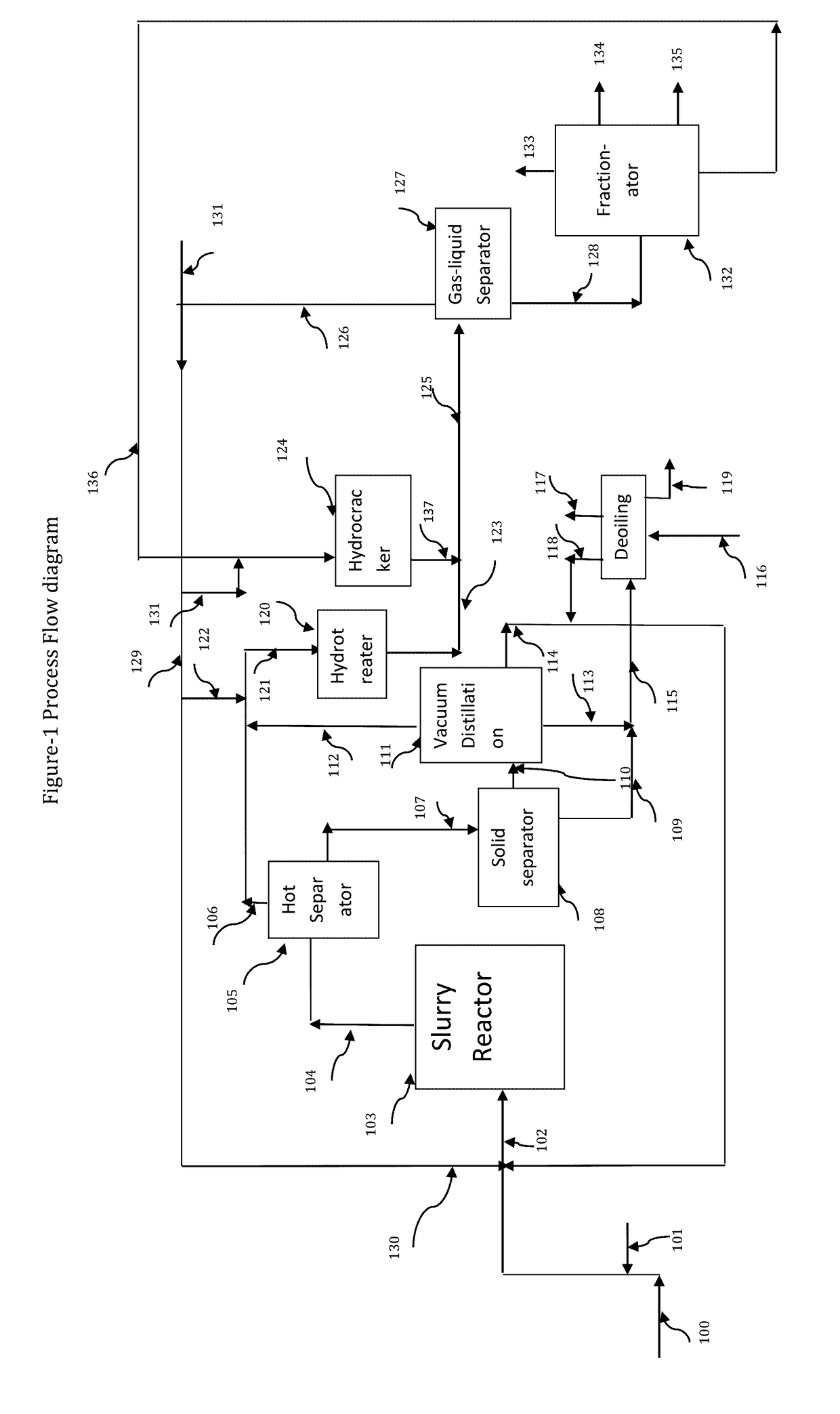
This patent describes a new catalyst and process for converting heavy oils into lighter products. The catalyst is a special iron compound that is dissolved in oil and can be easily handled. It has small metal particles that can penetrate the oil molecules and help break them open. This results in better dispersion and higher activity compared to traditional catalysts. The process involves using a slurry bed hydrocracking reactor and recycling liquid products to improve conversion and selectivity. The invention allows for the efficient and effective conversion of heavy oil into valuable liquid products.

Problems solved by technology

The catalyst being oil soluble avoids the requirement for solid handling and expensive and proprietary methods for manufacturing.

Method used


Image

  • Vacuum resid upgradation and graphite production
  • Vacuum resid upgradation and graphite production
  • Vacuum resid upgradation and graphite production

Examples


example 1

[0046]A feed suitable for SHC is characterized in Table-1. This feed was used in all the examples:

TABLE 1Characteristics of Feed stockPropertiesFeed(VR)Specific gravity, g / cc1.020ICAP Metals (ppm)Mo2.8Ni49V174Fe8.5CCR24.79S, wt %5.4Total N, ppm1400Heptane insolubles, wt %8.55

example 2

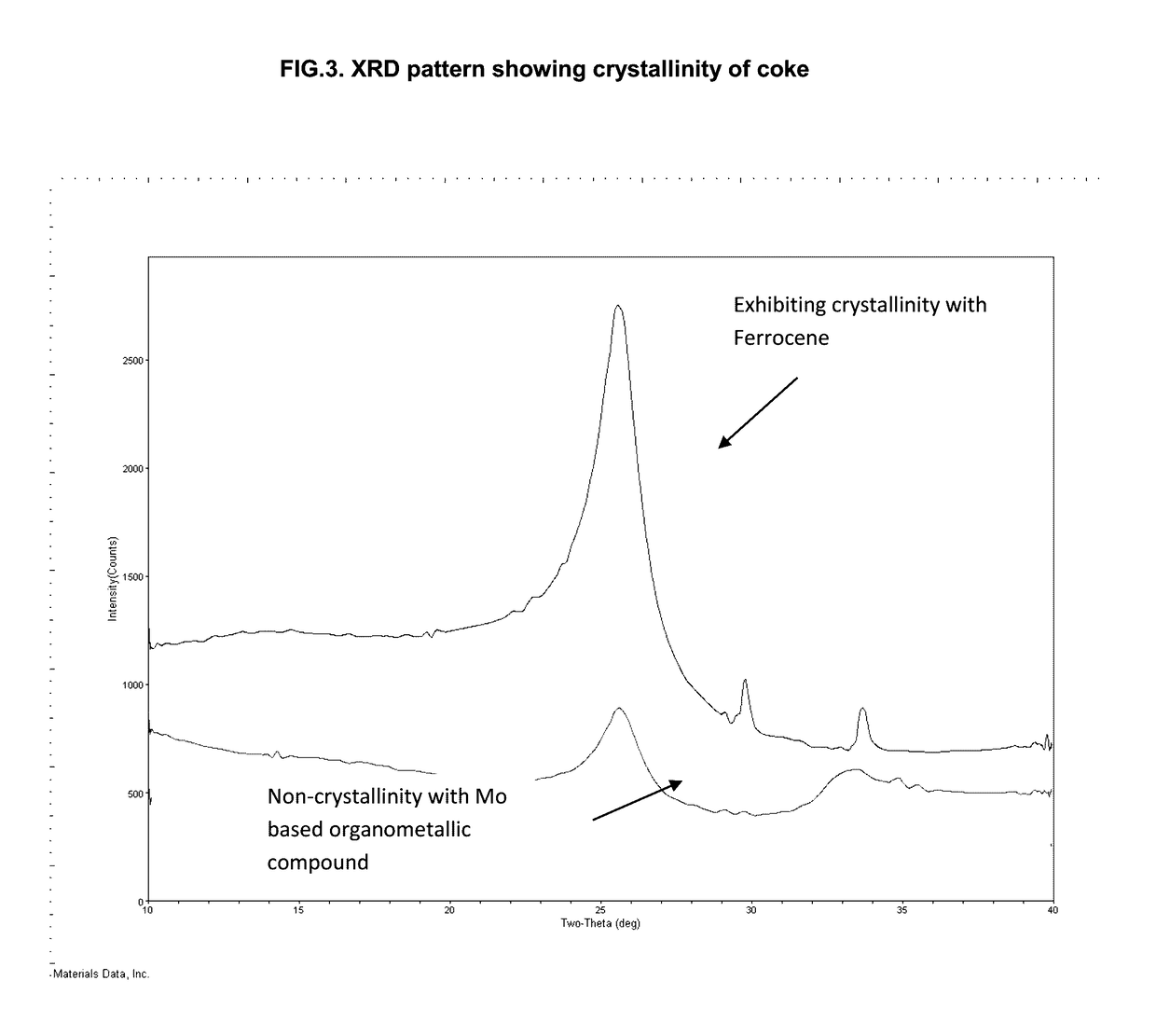
[0047]An oil soluble Mo based organometallic compound which acts as a hydrogenation catalyst was used. The catalyst was pretreated by adding 2 wt % sulfiding agent relative to the feed and catalyst and heating the mixture to 220° C. at 30 bar and charging the heated mixture at high temperature and high velocity through a 10 meter long tube in a 1 litre autoclave reactor using hydrogen gas within 15 minutes to activate the catalyst before heating the mixture to reaction temperature in the autoclave. In a typical experiment, 300 grams of vacuum resid of Example 1 was charged in a 1 litre autoclave with the catalyst concentration of 660 and 165 ppm on metal basis. In the example cited in Table 2, the autoclave was heated for 120 minutes at 180 bar at operation temperature. Hydrogen was continuously added through a sparger and passed through the reactor continuously at a rate of 350 Standard Litre Per Hour (SLPH) and removed through a back pressure valve to maintain pressure. The hydrog...

example 3

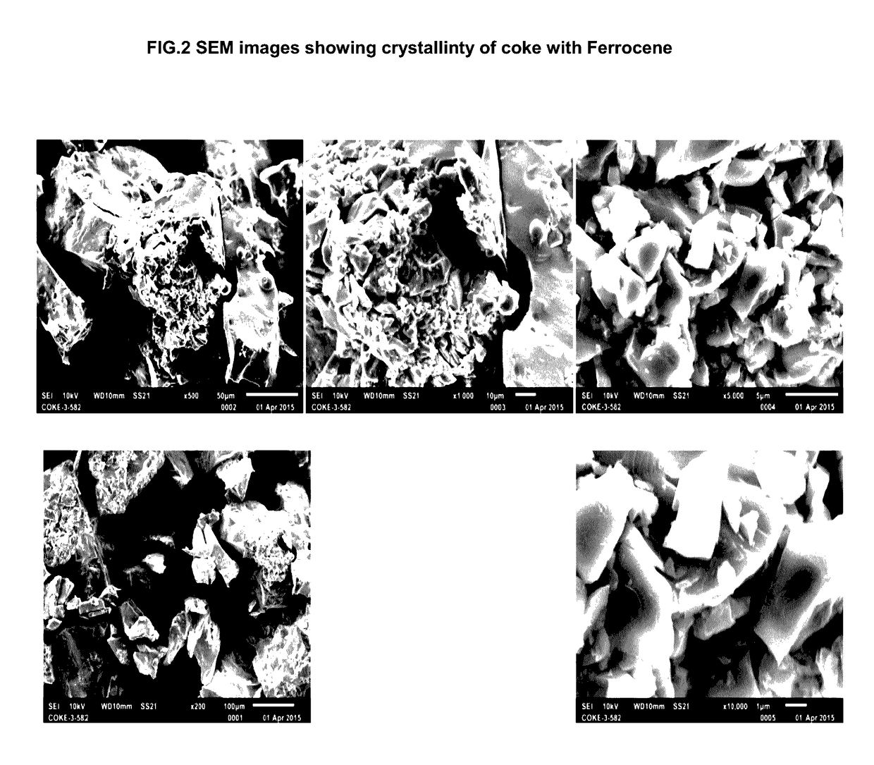
[0048]An oil soluble organometallic compound i.e. ferrocene which acts as a hydrogenation catalyst was used. The catalyst was pretreated by adding 2 wt % sulfiding agent relative to the feed and catalyst and heating the mixture to 220° C. at 30 bar and charging the heated mixture at high temperature and high velocity through a 10 meter long tube in a 1 litre autoclave reactor using hydrogen gas within 15 minutes to activate the catalyst before heating the mixture to reaction temperature in the autoclave. In a typical experiment, 300 grams of vacuum resid of Example 1 was charged in a 1 litre autoclave with the catalyst concentration of 330 and 660 ppm on metal basis. In the example cited in Table 2, the autoclave was heated for 120 minutes at 180 bar at operation temperature. Hydrogen was continuously added through a sparger and passed through the reactor continuously at a rate of 350 SLPH and removed through a back pressure valve to maintain pressure. The hydrogen stripped out the ...


PUM

PropertyMeasurementUnit
Temperatureaaaaaaaaaa

Abstract

The present invention discloses a catalyst and process for hydrocracking of heavy hydrocarbon oils having majority portion boiling above 525° C. in the presence of hydrogen. A process comprising first step of converting heavy oil into lighter products in the presence of catalyst and hydrogen in slurry phase is disclosed. The process further comprises recycling of part of liquid products (HVGO) along with fresh heavy oil for improving the product selectivity. This recycled HVGO is having high concentrations of aromatics compounds. The separation of particles generated during the reaction at reactor exit also avoids the chances of choking of downstream sections.

Description

BACKGROUND OF THE INVENTION[0001]There exist enormous quantities of heavy hydrocarbons such as heavy petroleum crude oils and tar sand bitumen (the heavy hydrocarbons extracted from tar sands), as well as residual heavy hydrocarbon fractions obtained from heavy hydrocarbon crudes such as atmospheric tower bottoms products, vacuum tower bottoms products, crude oil residuum and heavy vacuum gas oils. These heavy crudes and residual hydrocarbon streams contain large amounts of organometallic compounds, especially those containing nickel and vanadium, organosulfur and organonitrogen compounds, and asphaltenes (high molecular weight polycyclic, heptane insoluble materials). In addition, these heavy crude and residual hydrocarbons are viscous and as such require a greater degree of processing to convert them into liquid materials that can be transported easily.[0002]A number of alternate physical and chemical routes have been developed and are still being developed for converting heavy hy...

Claims


Application Information

Patent Timeline
IPC IPC(8): B01J37/08B01J23/745C10B57/04C10B55/00C10B57/06C10G65/12B01J23/28
CPCB01J37/086C10G65/12B01J23/745B01J23/28C10G2300/205C10B57/06C10B57/045C10G2300/703C10G2300/202C10B55/00B01J37/18B01J37/20C10G47/02C10G47/26B01J23/883C01B32/205B01J35/23
Inventor KUMAR, BRIJESHKUMAR, PRAVESHKUMAR, KAMALBUTLEY, GANESH VITTHALRAOSAU, MADHUSUDANDAS, BISWAPRIYA
Owner INDIAN OIL CORPORATION
Learn More