
Heat dissipation device

a heat sink and heat dissipation technology, applied in the direction of indirect heat exchangers, lighting and heating apparatus, tubular elements, etc., can solve the problems of slow and poor heat dissipation effect of heat sinks, adversely affecting the service life of chips, and low computation speed of chips, so as to improve heat dissipation efficiency and heat transfer

Active Publication Date: 2017-02-09
ASIA VITAL COMPONENTS SHENZHEN CO LTD
View PDF27 Cites 1 Cited by
  • Summary
  • Abstract
  • Description
  • Claims
  • Application Information

AI Technical Summary

Benefits of technology

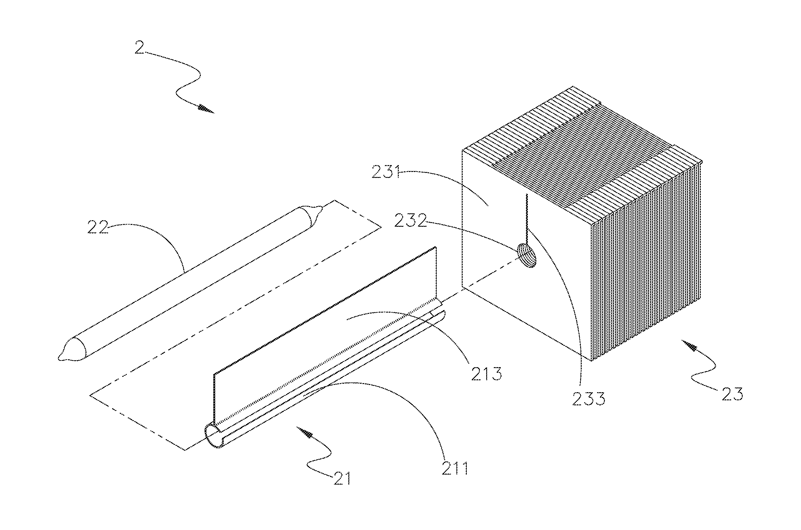
The present invention provides a heat dissipation device with significantly improved heat transfer and dissipation efficiency. The device can dissipate heat faster than existing devices. The heat pipes are fitted into a C-shaped fitting portion that has a first heat transfer portion integrated therein. The heat from a heat source is transferred quickly to the heat pipe and covering member, and then quickly to the first heat transfer portion. The first heat transfer portion provides an increased heat transfer area, enabling the device to have enhanced heat transfer and dissipation efficiency.

Problems solved by technology

The produced heat must be quickly removed from the electronic element, or the heat can lower the computation speed of chips.
In a worse condition, the heat can adversely affect the service life of the chips.
However, the conventional heat pipe usually has a round or an oval cross section, which provides only a point-to-point contact and accordingly, a very small contact area between the heat pipe and the heat radiation fins, resulting in slow and poor heat transfer effect of the heat sink.
In conclusion, the prior art heat dissipation device has the following disadvantages: (1) having low heat transfer effect; and (2) having poor heat dissipation efficiency.

Method used


Image

  • Heat dissipation device
  • Heat dissipation device
  • Heat dissipation device

Examples


Embodiment Construction

[0027]The present invention will now be described with some preferred embodiments thereof and by referring to the accompanying drawings. For the purpose of easy to understand, elements that are the same in the preferred embodiments are denoted by the same reference numerals.

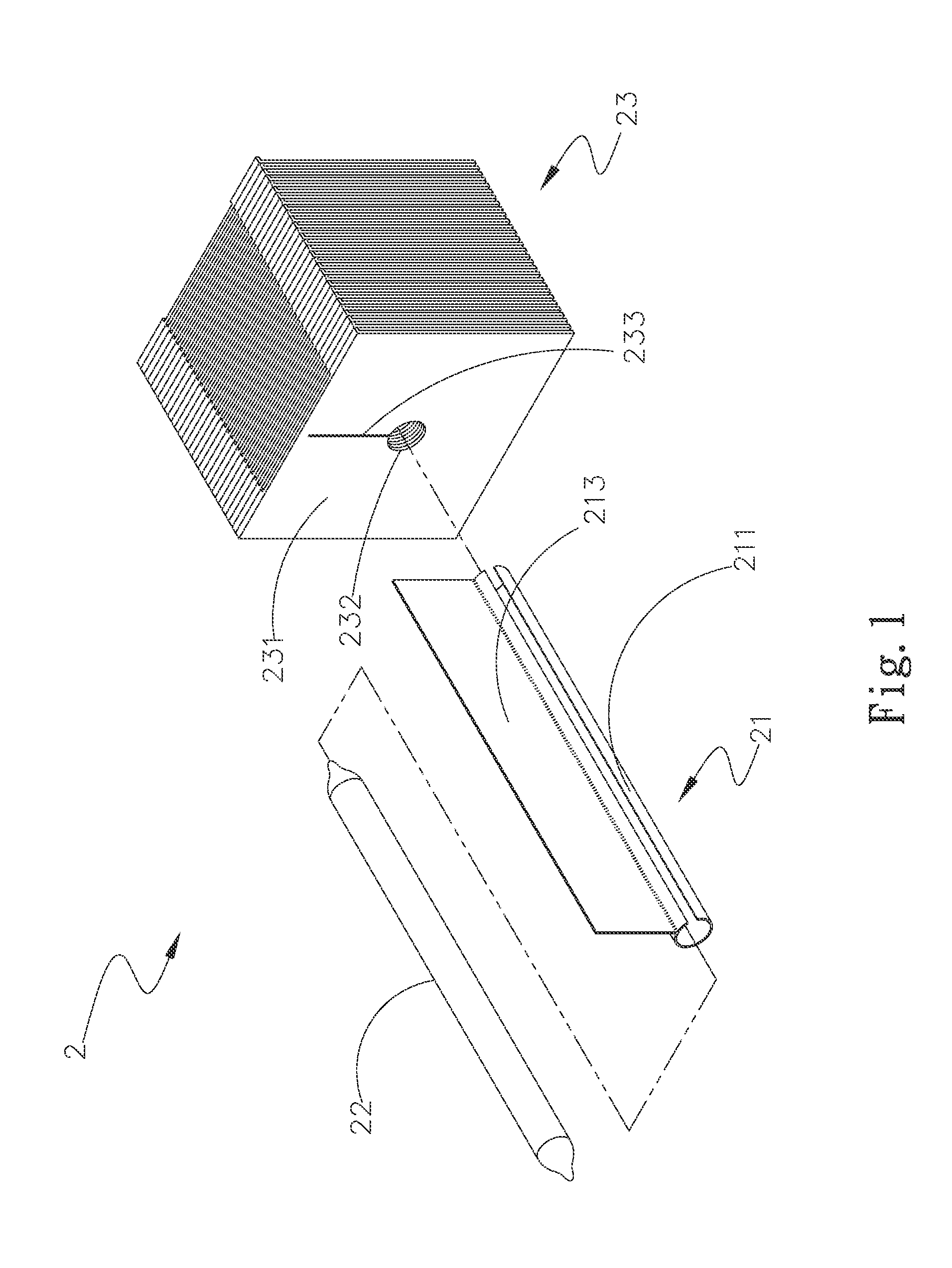
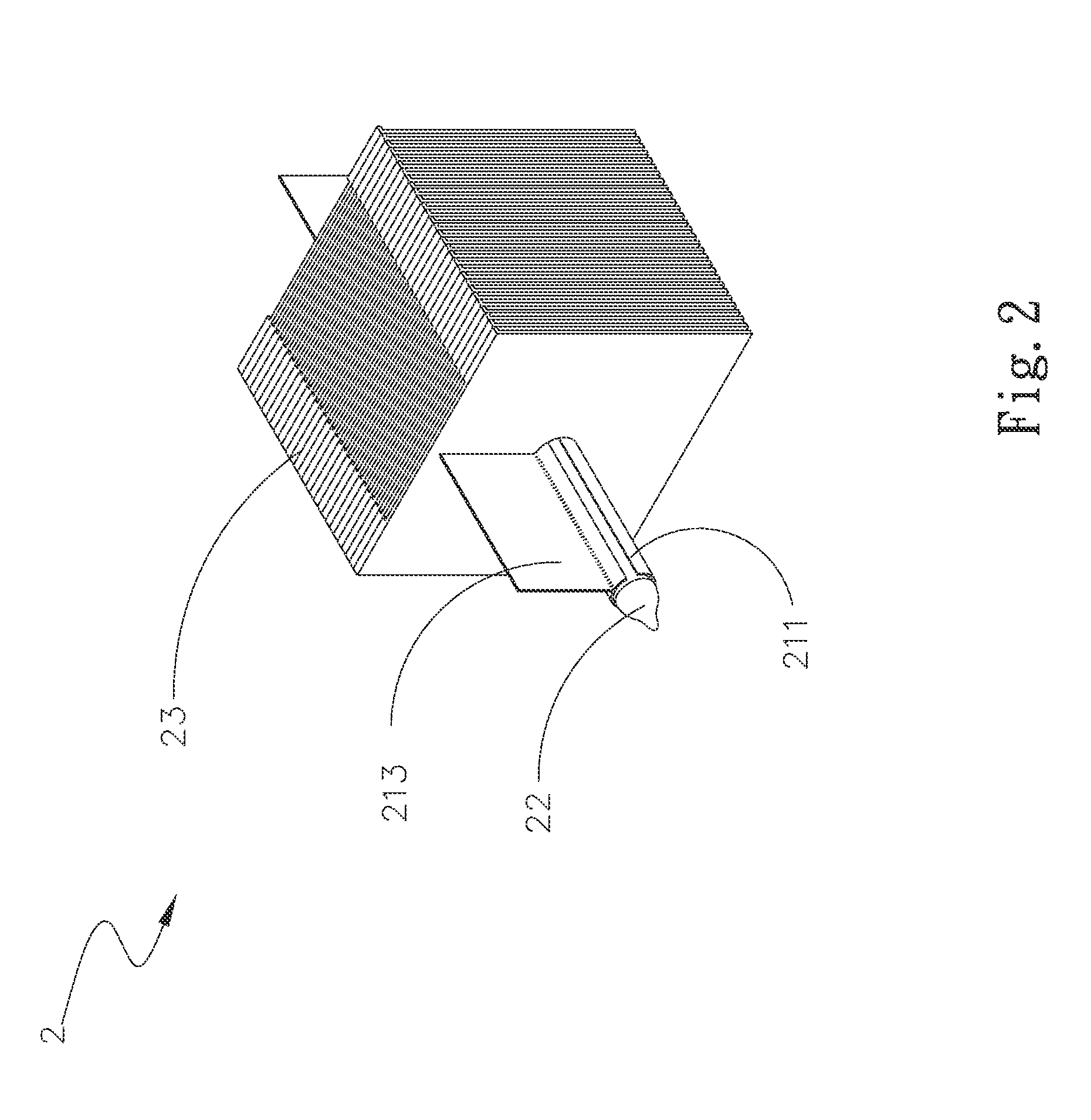
[0028]Please refer to FIGS. 1 and 2, which are exploded and assembled perspective views, respectively, of a heat dissipation device 2 according to a first preferred embodiment of the present invention, and to FIG. 3, which is a front view of FIG. 2. As shown, the heat dissipation device 2 includes a covering member 21, a heat pipe 22, and a heat dissipation unit 23. The covering member 21 has a C-shaped fitting portion 211. At least one first heat transfer portion 213 is integrally outwardly extended from a periphery of the C-shaped fitting portion 211. In the first embodiment, the first heat transfer portion 213 is an integral body axially extended along the C-shaped fitting portion 211. However, in a second emb...


PUM


Abstract

A heat dissipation device includes a covering member, a heat pipe, and a heat dissipation unit. The covering member has a hollow C-shaped fitting portion, in which the heat pipe is fitted to tightly connect to the covering member. At least one first heat transfer portion is outwardly extended from a periphery of the C-shaped fitting portion of the covering member. The heat dissipation unit has a plurality of parallelly spaced heat radiation fins, each of which has a through hole formed thereon, and at least one first locating slot is outwardly extended from the through hole. When the C-shaped fitting portion and the first heat transfer portion are respectively extended through the through holes and the first locating slots, the covering member is connected to the heat dissipation unit. With the first heat transfer portion, the heat dissipation device can have enhanced heat transfer and dissipation effect.

Description

FIELD OF THE INVENTION[0001]The present invention relates to a heat dissipation device, and more specifically, to a heat dissipation device having largely increased heat transfer effect and heat dissipation efficiencyBACKGROUND OF THE INVENTION[0002]With the advancement of technology, the number of transistors on per unit area of an electronic element is constantly increased to produce a largely increased amount of heat when the electronic element operates. Also, the operating frequency of the electronic element is higher and higher. Switching on / off of the transistors in operation generates heat as well, which also forms one reason why the electronic elements generate more heat than ever before. The produced heat must be quickly removed from the electronic element, or the heat can lower the computation speed of chips. In a worse condition, the heat can adversely affect the service life of the chips. To improve the heat dissipation efficiency of the electronic element, heat radiatio...

Claims


Application Information

Patent Timeline
IPC IPC(8): F28D15/02
CPCF28D15/02F28D15/0275F28F1/24F28F1/30
Inventor CHEN, CHIH-PENGSHEN, HUANG-PIN
Owner ASIA VITAL COMPONENTS SHENZHEN CO LTD
Learn More