
Method for reducing nitrogen oxide(s) and carbon monoxide from flue gases and flue gas composition

a technology of nitrogen oxide and carbon monoxide, which is applied in the direction of emissions prevention, combustion types, separation processes, etc., can solve the problems of nox, impede the reduction, and the thermal combustion process always generates nitrogen oxides, so as to reduce the residual oxygen amount, the effect of enhancing the efficiency of the burner and reducing the power consumption of the blower

Inactive Publication Date: 2016-10-20
OILON TECH OY
View PDF2 Cites 2 Cited by
  • Summary
  • Abstract
  • Description
  • Claims
  • Application Information

AI Technical Summary

Benefits of technology

The patent discusses a method for reducing emissions in flue gases from combustion systems. The method involves measuring the amount of residual oxygen after a three-way catalytic converter and adjusting the amount of combustion air to match this measurement. This results in a reduction of emissions and improved efficiency of the burner. Additionally, the patent describes a method for oscillating the ratio of combustion air to fuel, which further expands the effective operating range of the catalytic converter. By using a frequency transformer, the amount of residual oxygen can be minimized, resulting in improved burner efficiency and reduced power consumption. Overall, the patent provides technical means for achieving low emissions levels and improved performance in combustion systems.

Problems solved by technology

When an industrial burner is used for the combustion of liquid or gaseous fuels, there is a problem that the thermal combustion process always generates nitrogen oxides (NOx) because, at a high temperature (>1000° C.
Another problem in the thermal combustion process is that thermal combustion is never complete, but the flue gas is always left with unburned hydrocarbons (VOC) and carbon monoxide (CO) as a result of incomplete combustion.
Therefore, the emissions resulting from reducible (NOx) and oxidizable (HC and CO) reactions are generated in conflicting temperature conditions, hindering the reduction thereof.
Even with several possible burner adjustment methods available, there is none that would achieve a sufficiently low residual oxygen level required for flue gases by the method described in the discussed application.
By just regulating the rate of total fuel flow and total combustion air flow, it will be difficult to reach the required concentrations of residual oxygen prior to the catalytic zone as a result of physical, burner control technology-related, as well as hardware-related limitations.
Additionally, it was discovered, that while it was sometimes possible to attain stoichiometric fuel and air ratio in a mixer zone of a burner and thereafter a proper flue gas composition before delivering this flue gas composition into catalytic zone with above “existing technology” for example by regulating the air / fuel ratio supplied into a burner conventional technology, “it was practically impossible to maintain said proper composition of flue gases except for a very short time span.

Method used


Image

  • Method for reducing nitrogen oxide(s) and carbon monoxide from flue gases and flue gas composition
  • Method for reducing nitrogen oxide(s) and carbon monoxide from flue gases and flue gas composition
  • Method for reducing nitrogen oxide(s) and carbon monoxide from flue gases and flue gas composition

Examples


Embodiment Construction

[0077]As can be seen from FIG. 5 shows test results from 2.6 MW capacity industrial burner with applied catalytic flue gas treatment (Oilon laboratory Lahti, Finland). The burner construction and function was similar as defined in claims. As can be seen from FIG. 5 NOx average was through measuring period <2 ppm (dry) and CO average was through measuring period <4 ppm (dry). These results confirm that using the burner of the present invention one can achieve very low NOx and CO emissions.

[0078]FIG. 6 shows a flue gas concentration before a three-way catalytic converter which enables most efficient conversion of NOx and CO in a catalytic zone of said a three-way converter. The following reactions take place in a three-way converter:

[0079]Main oxidation reactions:

CO+0.5O2—CO2

CH4+2O2-CO2+2H2O

[0080]Main reduction reactions:

2NO+2CO-N2+2CO2

4NO+CH4-2N2+CO2+2H2O

[0081]As can be seen from FIG. 6, air to fuel ratio (a) should be almost stoichiometric in flue gases before a three-way catalytic...


PUM


Abstract

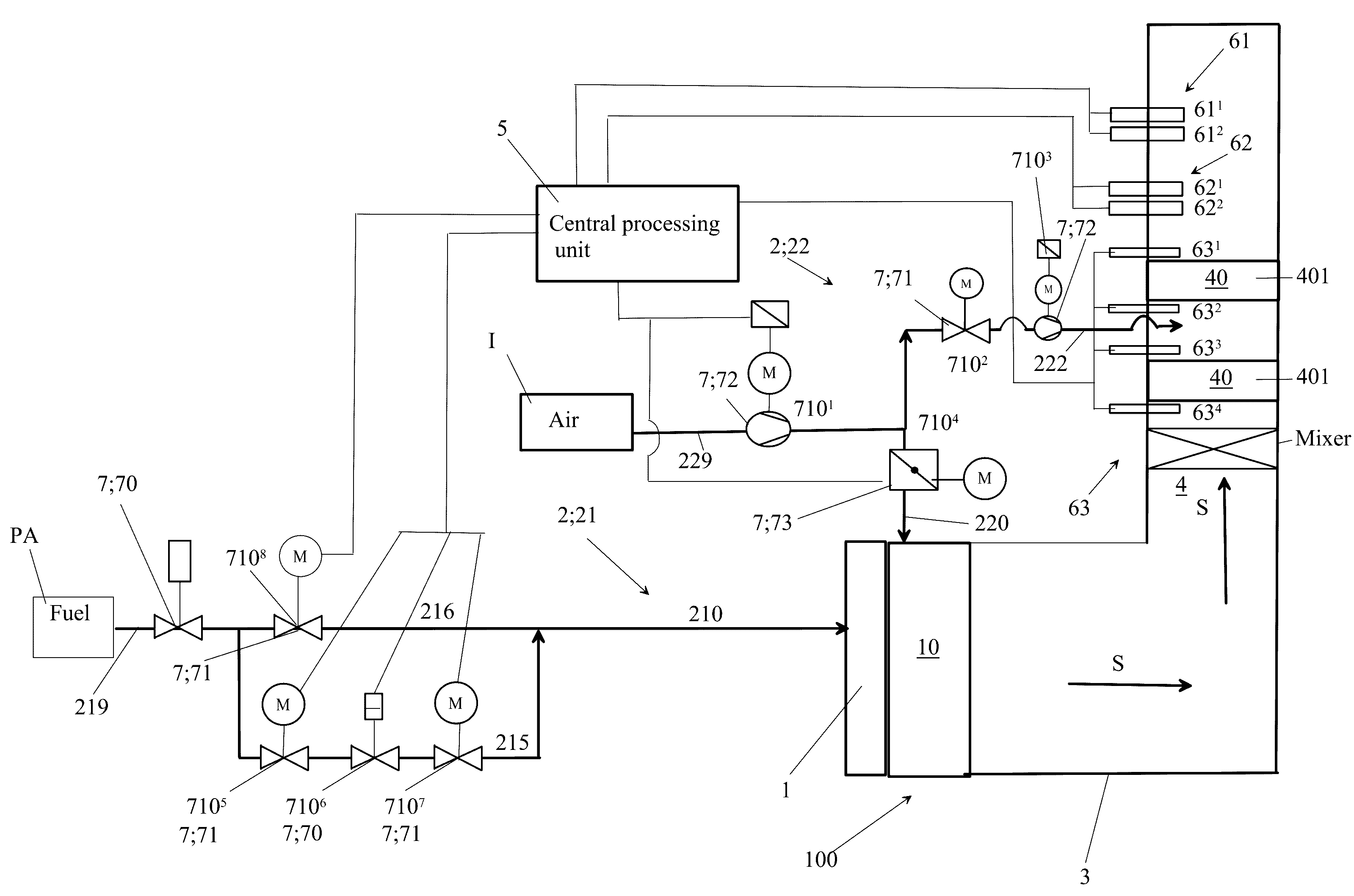
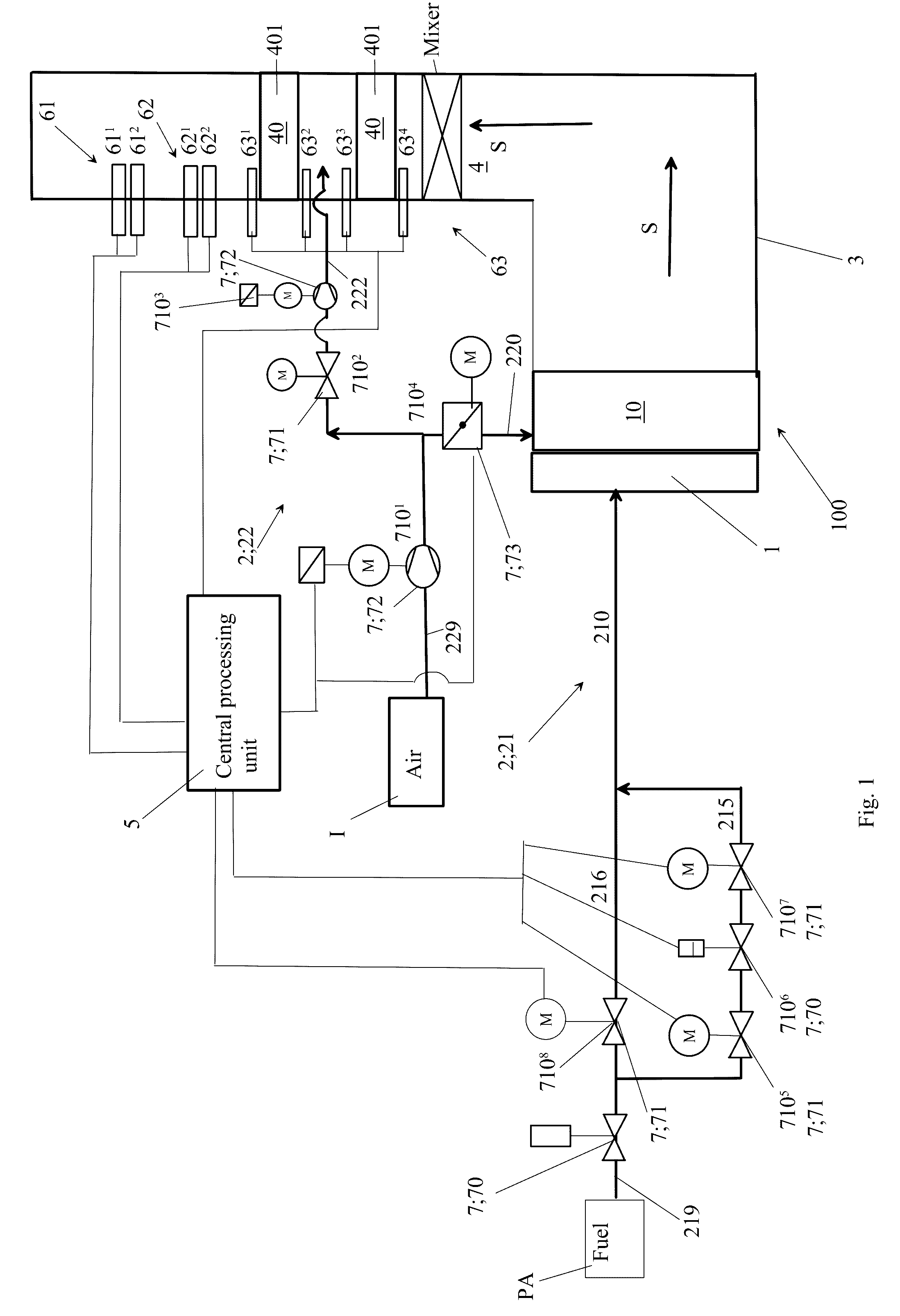
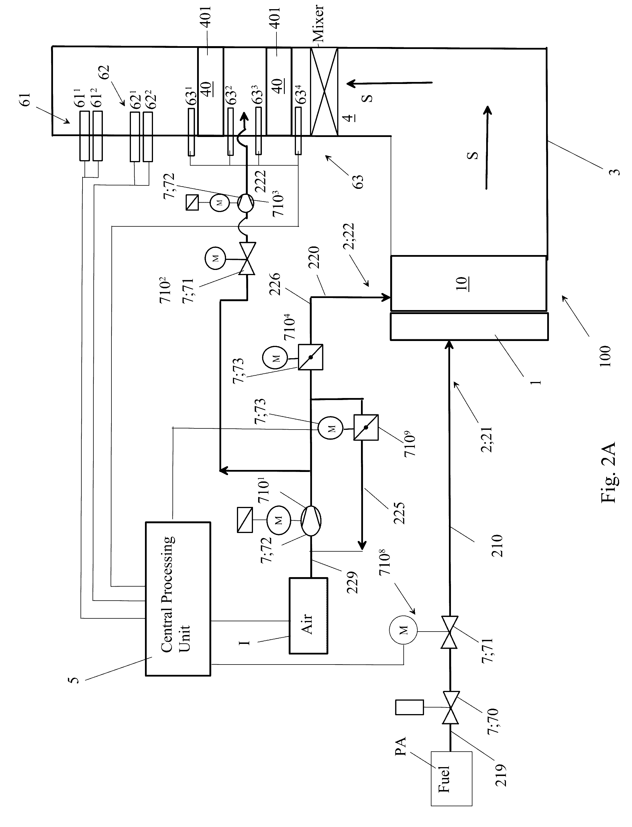
A method for reducing nitrogen oxide(s) and carbon monoxide from flue gases of an industrial burner adapted to burn gaseous and / or liquid fuel is disclosed. The burner comprises burner automation containing measuring instruments, and a mixing zone accompanied by a combustion chamber. The burner automation is in communication with measurement instruments of flue gas conduit. The combustion chamber or flue gas conduit has two catalytic zones of at least one three-way catalytic converter(s). The catalytic zones are successive in progressing direction of flue gases. An inlet flow (QI, QItot) of combustion air and an inlet flow (QPA, QPAtot) of fuel is delivered into the mixing zone. The flue gases are generated in the combustion chamber by combusting air and fuel delivered into the mixing zone. The amount of residual oxygen is measured in flue gases by a lambda-sensor. The flue gases are directed to at least one three-way catalytic converter(s). The inlet flow (QI, QItot) of combustion air and the inlet flow (QPA, QPAtot) of fuel arriving in the mixing zone is adjusted by the burner automation, so that the mean amount of residual oxygen in moles compared to mean amount of carbon monoxide in moles, is 0.5 / 1 (mole / mole) and O2 within the range of 0.01-0.50 vol-% in flue gases prior to or at the first catalytic zone of the at least one three-way converter. Supplementary air is delivered between the first and the second catalytic zones of the three-way converter or between catalytic zones of two successive three-way catalytic converters, so that concentration in the flue gases after said catalytic zones is within range of 0-9 ppm for NOx and within a range of 0-100 ppm.

Description

PRIORITY[0001]This application claims priority of the Finnish national application number FI20155279 filed on Apr. 14 2015, the contents of which are incorporated herein by reference in entirety.FIELD OF THE INVENTION[0002]The invention relates to a methods and devices to reduce nitrogen oxide(s) and carbon monoxide from flue gasses of industrial burners as well as to flue gas compositions.[0003]The invention relates to a method as set forth in the claim 1 for reducing nitrogen oxide(s) and carbon monoxide from flue gases of an industrial burner which is intended for a gaseous and / or liquid fuel.[0004]The invention relates also to a flue gas composition in the claim 17.[0005]The invention relates further to burner automation, which can be used in the burner of the invention.BACKGROUND OF THE INVENTION[0006]One generally known industrial burner model, which is intended for gaseous and / or liquid fuels, comprises in connection with the windbox a fuel supply conduit for the combustion h...

Claims


Application Information

Patent Timeline
IPC IPC(8): F23J15/02F23N1/02F23N5/00
CPCF23J15/02F23N1/022F23N5/006F23D11/36F23D14/60B01D53/8625B01D53/864F23D14/46F23D17/002F01N3/101F23N1/002F23N3/082F23J2215/101F23J2215/40F23J2219/10F01N2560/022F01N2560/025F01N2560/026F01N2590/10Y02T10/12F23D2208/005
Inventor TULOKAS, TERO
Owner OILON TECH OY
Learn More