
Process and Apparatus for Cleaning Raw Product Gas

a technology for cleaning raw products and raw materials, applied in the direction of gas purification with selectively adsorbent solids, gasification process details, etc., can solve the problems of serious problems for the operation of downstream equipment, complex overall gasification process, and a significant component of the overall gasification capital and operating costs

Active Publication Date: 2016-10-20
RENERGI PTY LTD
View PDF1 Cites 6 Cited by
  • Summary
  • Abstract
  • Description
  • Claims
  • Application Information

AI Technical Summary

Benefits of technology

The invention relates to a method and apparatus for cooling and cleaning the raw product gas produced from the gasification of carbonaceous material, such as biomass. The method involves contacting the raw product gas with a flow of char or char-supported catalyst at a high temperature of about 800°C or more, which reduces the temperature of the raw product gas to a range of 700°C to 750°C through endothermic reactions. Cooling the product gas then further reduces the temperature to less than 250°C, such as 250°C or less. The apparatus includes a gasifier for gasifying carbonaceous material and a cooling system for cleaning the raw product gas. Overall, the invention allows for efficient cooling and cleaning of the raw product gas produced from gasification, which improves the quality and efficiency of the overall gasification process.

Problems solved by technology

These low-rank fuels, however, are a complex mixture of organic and inorganic species and the resulting raw product gas is typically contaminated with tarry residues, fine particulates and alkali and alkaline earth metallic (AAEM) species as well as trace inorganics such as manganese, boron, copper, iron, molybdenum and zinc, and pollutant-forming species (e.g. NH3, HCN, NOx, SOx and H2S).
Tarry residues in the product gas tend to condense at lower temperatures in the downstream equipment, thereby causing operational difficulties.
The inorganic species may also be volatilised into the product gas and cause serious problems for the operation of downstream equipment, including corrosion / erosion of turbine / engine components used for electricity generation.
The removal of various undesirable components such as tarry materials, AAEM vapour, particulates and H2S / NH3 / HCl / HCN from the gasification product gas contributes to the overall gasification process complexity and forms a significant component of the overall gasification capital and operating costs.
However, the raw product gas must be cooled down first, causing some species to condense.
It is also challenging to effectively recover heat from the raw product gas because of the unavoidable deposition of these species on the heat exchanger surface.
Furthermore, the scrubbing operation merely transfers the tarry components and other undesirable species in the raw product gas into the water to create a liquid waste stream which requires expensive treatment prior to disposal.
Many rural areas, where a biomass gasification system could be installed, for example, for distributed power generation, do not have a suitable source of water for the scrubbing operation.
The use of other liquids such as biodiesel would be expensive, not only because of the purchasing cost but also because of the cost to transport the liquid to remote regions.
The complex reactions involving these inorganic species during gasification may turn them into chemically very stable species such as silicates and consequently they become unusable or less suitable for the growth of new biomass even if the ash is returned back to the land.
Alternatively, they may volatilise and end up as sludge (after the scrubbing operation) or reside in other forms of wastes which cannot be returned to the field.
The loss of these nutrients from the land will deteriorate the long-term productivity and sustainability of agricultural land.
In fact, it has been suggested that a significant fraction of biomass costs will be associated with additional costs to buy fertilisers to replenish the nutrients lost from the land due to the use of biomass as an energy source.
Unfortunately, not all nutrients are replenished by these fertilisers.

Method used


Image

  • Process and Apparatus for Cleaning Raw Product Gas
  • Process and Apparatus for Cleaning Raw Product Gas
  • Process and Apparatus for Cleaning Raw Product Gas

Examples


Embodiment Construction

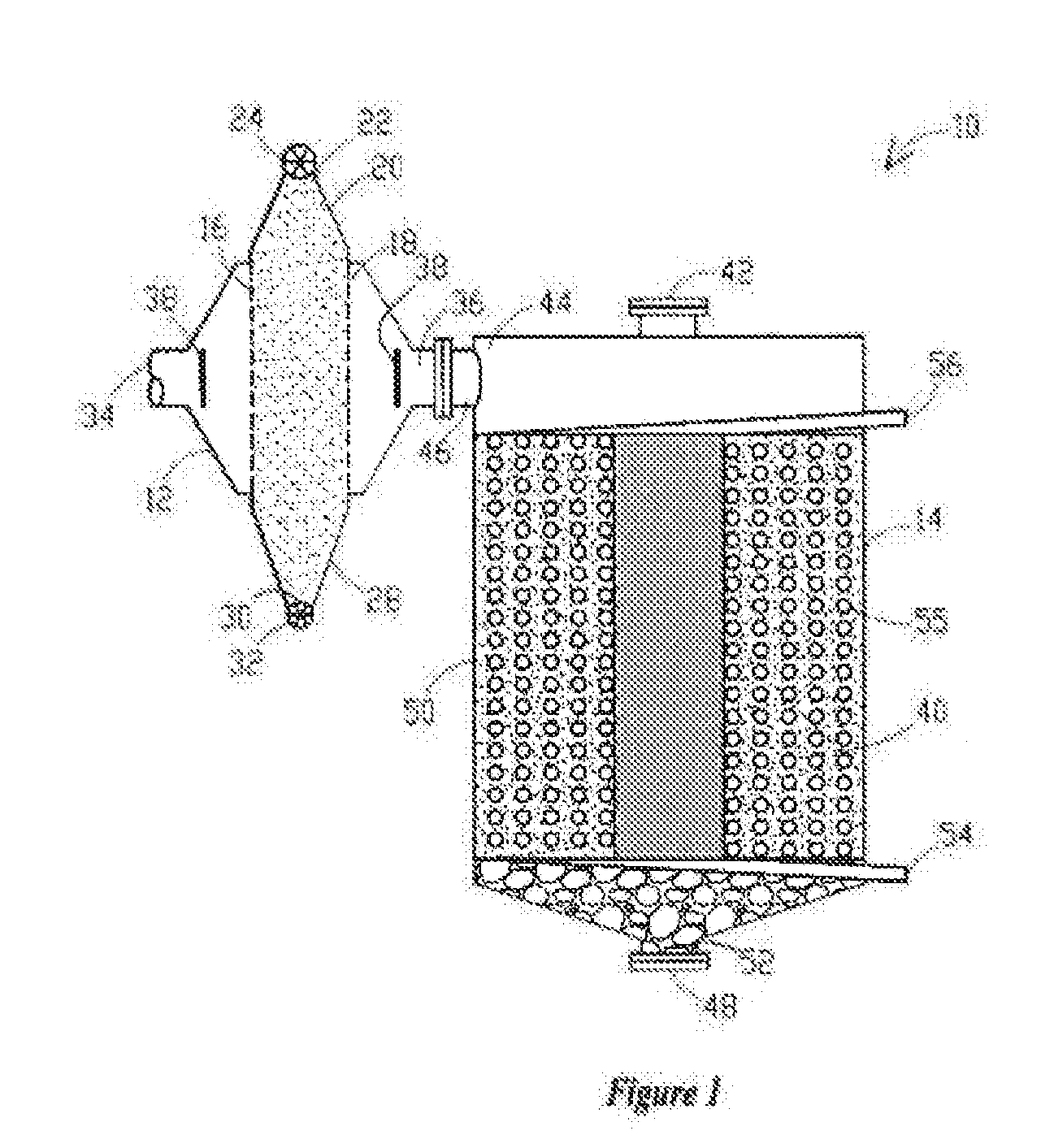
[0037]Embodiments of the present invention relate to a process for cleaning a raw product gas and an apparatus 10, 10′ for cleaning a raw product gas as described with reference to FIGS. 1, 2a and 2b and 3.

[0038]In its broadest form, the process for cleaning a raw product gas comprises the steps of:[0039]a) contacting the raw product gas with a flow of catalyst; and[0040]b) cooling the resulting product gas via heat exchange with a heat exchange medium in the presence of char or a solid adsorbent medium.

[0041]The term ‘raw product gas’ is used herein to refer to a product gas produced by gasifying a carbonaceous material (gasification), in particular a low-rank carbonaceous material such as biomass, that contains contaminants such as tarry residues, condensable light organics, fine particulates, volatilised inorganic species inherent in the carbonaceous material and pollutant-forming species (e.g. NH3, HCN, NOx, SOx, and H2S) which form during gasification.

[0042]Gasification is the ...


PUM

PropertyMeasurementUnit
Flow rateaaaaaaaaaa
Lengthaaaaaaaaaa
Heataaaaaaaaaa

Abstract

The present disclosure provides a process for cleaning raw product gas. The process includes contacting the raw product gas with a flow of catalyst to reform organic contaminants and inorganic contaminants in the raw product gas and to remove particulates. Further, the process includes cooling the resulting product gas via heat exchange with a heat exchange medium in the presence of char or a solid adsorbent medium to condense remaining organic contaminants and inorganic contaminants on the char or solid adsorbent medium and to filter out fine particulates.

Description

FIELD OF THE INVENTION[0001]A process and an apparatus for cleaning raw product gas are disclosed. Particularly, though not exclusively, a process and an apparatus are disclosed for cleaning a raw product gas produced by gasifying a carbonaceous material such as biomass and coal.BACKGROUND OF THE INVENTION[0002]Gasification refers to the conversion of a solid or liquid material, such as a carbonaceous material, into a gaseous fuel otherwise known as product gas. Gasification is of interest for many low-emission technologies in chemical and energy industries.[0003]Gasification can be applied to a wide range of carbonaceous materials. In particular, low-rank carbonaceous fuels such as brown coal (lignite), peat, biomass and solid wastes are particularly suitable for gasification due to their high gasification reactivities. These low-rank fuels, however, are a complex mixture of organic and inorganic species and the resulting raw product gas is typically contaminated with tarry residue...

Claims


Application Information

Patent Timeline
IPC IPC(8): C01B3/58C10K1/32C10J3/58C10K1/04B01D53/04C10J3/84
CPCC01B3/58C10J2300/1618C10J3/84C10J3/58C10K1/046C10K1/32C01B2203/0435C01B2203/042C01B2203/0883C01B2203/1082C01B2203/1047C01B2203/1058C01B2203/146B01D2253/102B01D2255/20738B01D2255/20753B01D2257/7027C10J2300/094C10J2300/0916B01D53/04C01B3/56C01B2203/0227C01B2203/0465C01B2203/048C10J3/06C10J2300/093C10J2300/1853B01D2257/304B01D2257/406B01D2257/408Y02P20/129
Inventor LI, CHUN-ZHUGUNAWAN, RICHARDDONG, LI
Owner RENERGI PTY LTD
Learn More