Induction heating coil, and an apparatus and method for manufacturing a worked member

a technology of induction heating coil and worked member, which is applied in the direction of heat treatment apparatus, electric/magnetic/electromagnetic heating, furnaces, etc., can solve the problems of difficult to uniformly heat the steel tube b>1/b> in the circumferential direction, and the inability to rotate the steel tube b>1, so as to reduce the overall length of the coil and increase the heating efficiency

Active Publication Date: 2016-09-29
NIPPON STEEL CORP
View PDF27 Cites 0 Cited by
  • Summary
  • Abstract
  • Description
  • Claims
  • Application Information

AI Technical Summary

Benefits of technology

[0013]The manufacturing apparatus 0 can process a steel tube 1 with good accuracy. In order to increase the bending accuracy by the manufacturing apparatus 0, the heated width in the axial direction of the steel tube 1 is preferably as narrow as possible. This heated width increases as the number of turns of the induction heating coil increases. Therefore, the number of turns of the induction heating coil 5 is preferably made as small as possible in order to decrease the heated width.
[0015]FIG. 7 is an explanatory view showing one example of an induction heating coil 5 based on a conventional technical concept. FIG. 7(a) is a perspective view of the induction heating coil 5. FIG. 7(b) is a perspective view which is drawn with an increased spacing in the direction parallel to the axial direction of a steel tube 1 between the body 9-1 of the first turn of the induction heating coil 5 and the body 9-2 of the second turn for easy understanding of the structure of the induction heating coil 5. FIG. 7(c) is an explanatory view showing a projection of the induction heating coil 5 in the axial direction of the steel tube 1, with the solid arrows showing the direction of current in the body 9-1 of the first turn and the dashed arrows showing the direction of current in the body 9-2 of the second turn. FIG. 7(d) is an explanatory view showing an example of the temperature distribution in a numerical analysis simulation of a steel tube 1 heated using the induction heating coil 5.
[0022]An object of the present invention is to provide an induction heating coil which can stably heat a metal material such as a steel tube uniformly in its circumferential direction and in a narrow range in its axial direction. Another object of the present invention is to provide an apparatus and method for manufacturing a worked member which can stably and reliably manufacture a worked member having high dimensional accuracy using this induction heating coil.
[0028]In an induction heating coil based on a conventional technical concept, it was a common technical knowledge to design in such a manner that the separation between the member being heated and the coil was uniform and such that the overall length of the coil was minimized in order to increase the heating efficiency. However, as shown by FIG. 1, an induction heating coil according to the present invention has a shape which is markedly different from the shape resulting from the common technical knowledge of those skilled in the art. Namely, the present invention was completed by placing the most emphasis on making the number of coil turns uniform in the circumferential direction without regard to an increase in the overall coil length or in the distance (separation) between the coil and a member being heated, and it achieves the unexpected effect that it can uniformly heat the outer periphery of a non-rotating member being heated.
[0032]According to the present invention, it becomes possible to stably heat a metal material uniformly in the circumferential direction and in a narrow region in the lengthwise direction, so a worked member can be stably and reliably manufactured with a high dimensional accuracy.

Problems solved by technology

However, in this manufacturing apparatus 0, it is not possible to rotate a steel tube 1 around its central axis due to limitations on the range of movement of the movable roller die 4 which moves downstream of the support mechanism 2.
As a result, it is difficult to uniformly heat the steel tube 1 in the circumferential direction.

Method used


Image

  • Induction heating coil, and an apparatus and method for manufacturing a worked member
  • Induction heating coil, and an apparatus and method for manufacturing a worked member
  • Induction heating coil, and an apparatus and method for manufacturing a worked member

Examples


example

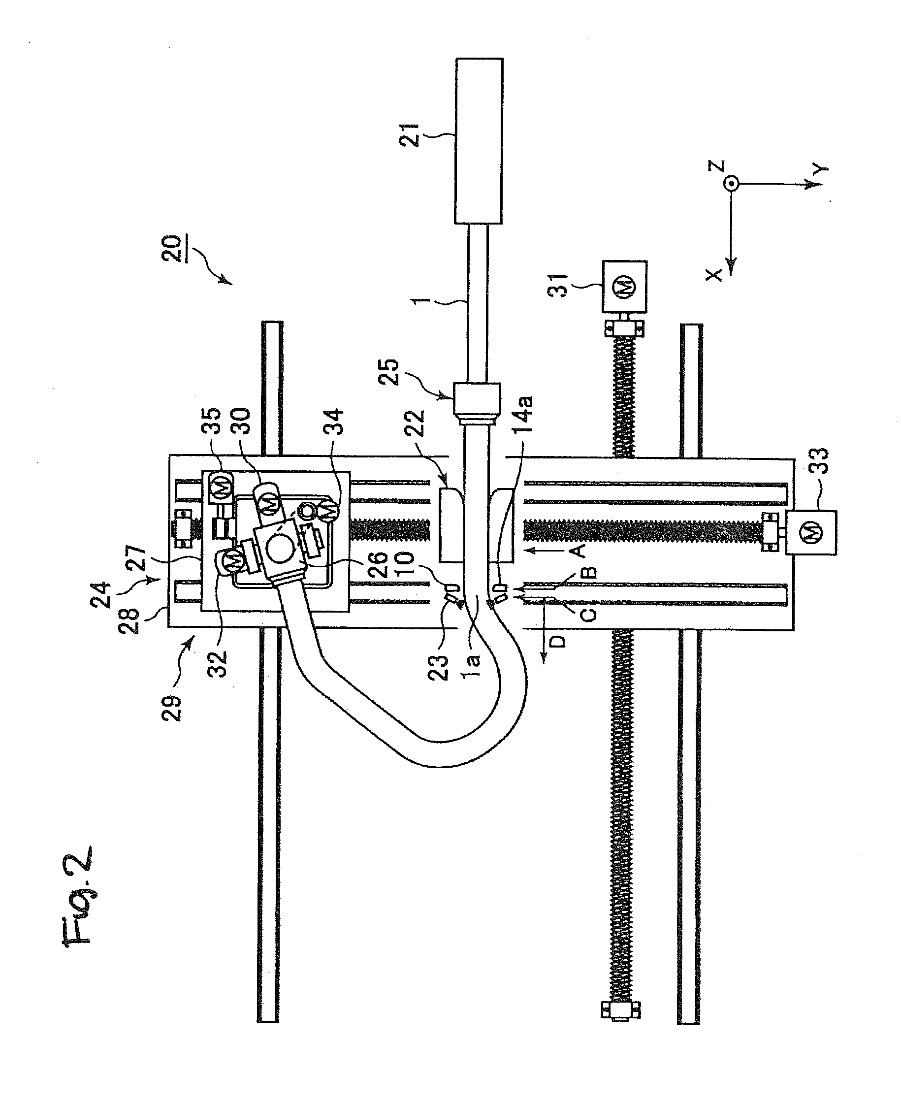
[0158]Using a manufacturing apparatus in which the induction heating coil 10 shown in FIG. 1 was applied to the manufacturing apparatus 0 shown in FIG. 6 and a manufacturing apparatus in which the comparative example of an induction heating coil 5 shown in FIG. 7 was applied to the manufacturing apparatus 0 shown in FIG. 6, induction heating was carried out on a steel tube 1 of plain steel having an outer diameter of 31.8 mm and a wall thickness of 1.8 mm while feeding the steel tube 1 in its axial direction without rotation at a feed speed of 80 mm / sec by passing it through the interior of induction heating coil 10 or 5. A plurality of thermocouples were mounted at two locations P1 and P2 in the circumferential direction of the steel tube 1, and the temperature of the steel tube 1 during heating was measured while feeding the steel tube 1.

[0159]FIG. 4 is a graph showing the results for the example of the present invention, and FIG. 5 is a graph showing the results for the comparati...


PUM

PropertyMeasurementUnit
tensile strengthaaaaaaaaaa
temperatureaaaaaaaaaa
wall thicknessaaaaaaaaaa

Abstract

An induction heating coil for stably heating a steel tube which is being fed in its axial direction without rotating, the heating being uniform in the circumferential direction and in a narrow range in the axial direction has at least two 1-turn coils in the form of a first turn coil body and a second turn coil body. The inner peripheral length Ln (the non-effective coil length) where the effective number of coil turns is less than the total number of coil turns when the coil is projected in the axial direction and the inner peripheral length LO of the projected coil bodies (the inner coil length) satisfy Ln / LO <0.05. First and second coil bodies have insulating portions on their connecting portions, and the insulating portions are present in locations separated by a central angle of 5-45° measured from the center of the coil bodies.

Description

TECHNICAL FIELD[0001]This invention relates to an induction heating coil and an apparatus and method for manufacturing a worked member. The present invention relates to an induction heating coil which is suitable for use when manufacturing a quenched steel material such as a quenched steel tube, an apparatus for manufacturing a worked member having this induction heating coil, and a method of manufacturing a worked member using this induction heating coil.BACKGROUND ART[0002]Strength members, reinforcing members, and structural members made of metal are used in automobiles and various types of machines A high strength, a low weight, and a small size are demanded of these members. In the past, these members have been manufactured by welding of press worked steel parts, punching of thick steel plates, forging of aluminum alloys, and similar methods. Reductions in weight and size achievable by these manufacturing methods are reaching a limit.[0003]In order to further decrease their wei...

Claims


Application Information

Patent Timeline
Patent Type & Authority Applications(United States)
IPC IPC(8): B21D7/16C21D1/42C21D9/08H05B6/36
CPCB21D7/162H05B6/36C21D9/085C21D1/42B21D7/165C21D9/08C21D11/00H05B6/104H05B6/44Y02P10/25H05B6/10
Inventor OKADA, NOBUHIROTOMIZAWA, ATSUSHISHIMADA, NAOAKI
Owner NIPPON STEEL CORP
Why Eureka
Try Eureka