
Method for producing a directly printed panel

a technology of printed panels and panels, applied in the field of panels, can solve the problems of annoying running noises, inconvenient use, and high cost of pvc floors, and achieve the effect of substantially more expensive than conventional laminate panels

Pending Publication Date: 2016-07-14
XYLO TECH AG
View PDF6 Cites 18 Cited by
  • Summary
  • Abstract
  • Description
  • Claims
  • Application Information

AI Technical Summary

Benefits of technology

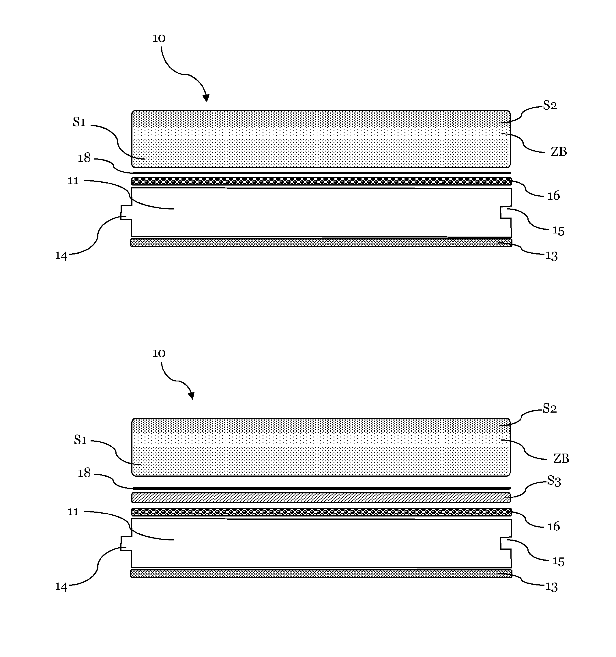
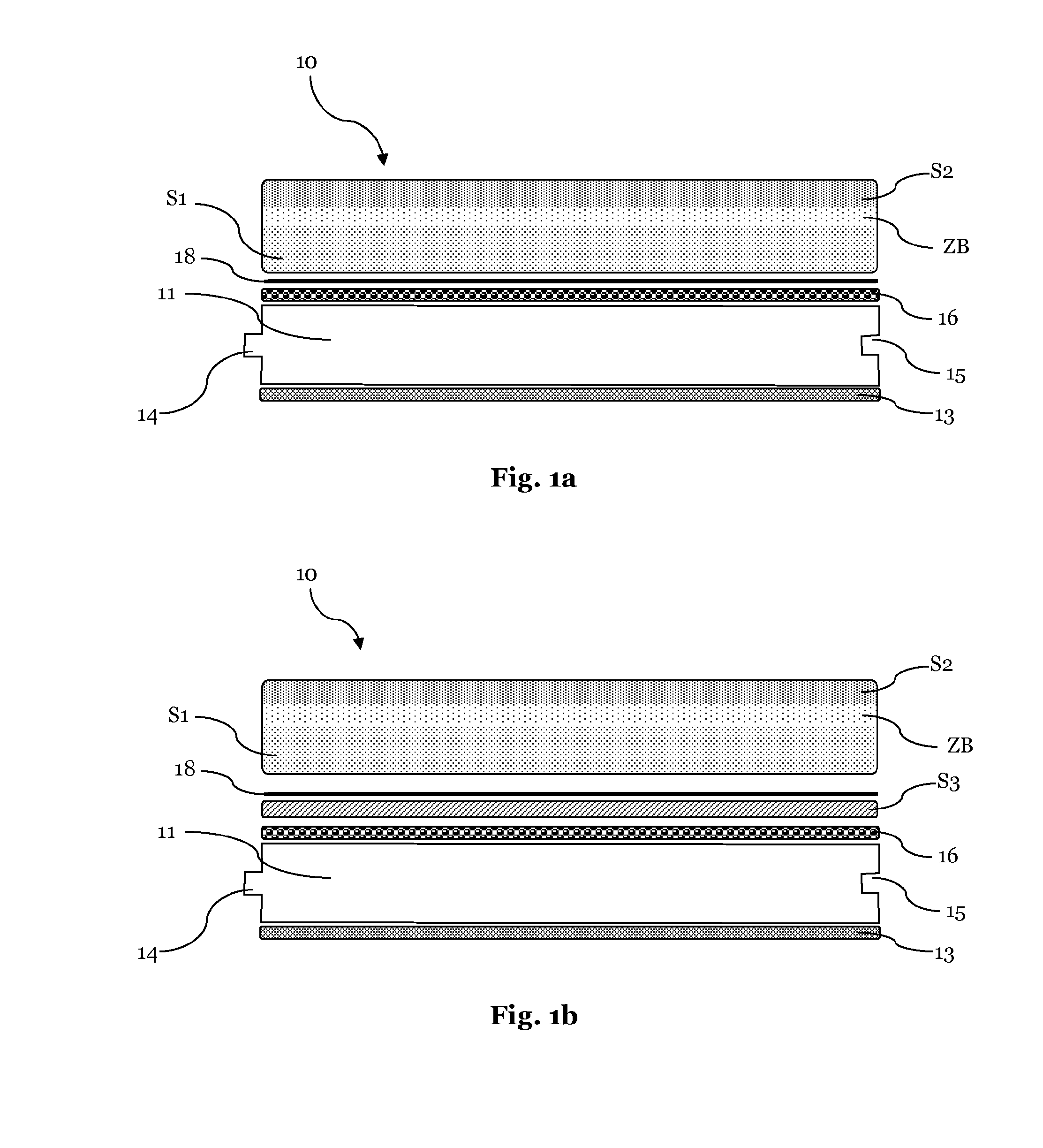
The invention is a layer system for panels that allows for a soft and warm haptic impression and has improved acoustic properties. The layer system includes a first elastic layer that is soft and has a low hardness, a second layer that has a higher hardness, and an intermediate area that has a gradual hardness between the first and second layers. The layer system can be applied to panels using a wet-on-wet method, which automatically creates a soft and warm surface. The invention also provides a method for producing the layer system that allows for individual customization. The layer system can be used with different support plates and materials, such as MDF, HDF, PVC, cement fiber, WPC, or parquet plates. Additionally, a decorative layer can be added between the front side and the first layer for a more visually appealing appearance.

Problems solved by technology

A disadvantage, however, are typically the acoustic properties of laminate panels, which cause annoying running noises, particularly when used as floor covering.
This melamine surface is also found as cold and inconvenient.
However, for generating surfaces of optically high-quality such PVC floors must be processed relatively expensive and are therefore substantially more expensive than conventional laminate panels, at least if they should comprise a similar optical quality.
The disadvantage of PVC panels is that deep scratches occur fast in the soft surface with intensive use which disturb the optical image.
Further, the disadvantage is that the PVC floors are not uncritical from ecological aspect.
They contain harmful plasticizers (“Weichmacher”) and chlorine is known to be very dangerous (e.g. chlorine dioxin formation, “Chlordioxinbildung”) in the case of fire.
However, they have disadvantages similar to laminate panels concerning the acoustic properties as well as haptic.

Method used


Image

  • Method for producing a directly printed panel
  • Method for producing a directly printed panel
  • Method for producing a directly printed panel

Examples


example 1

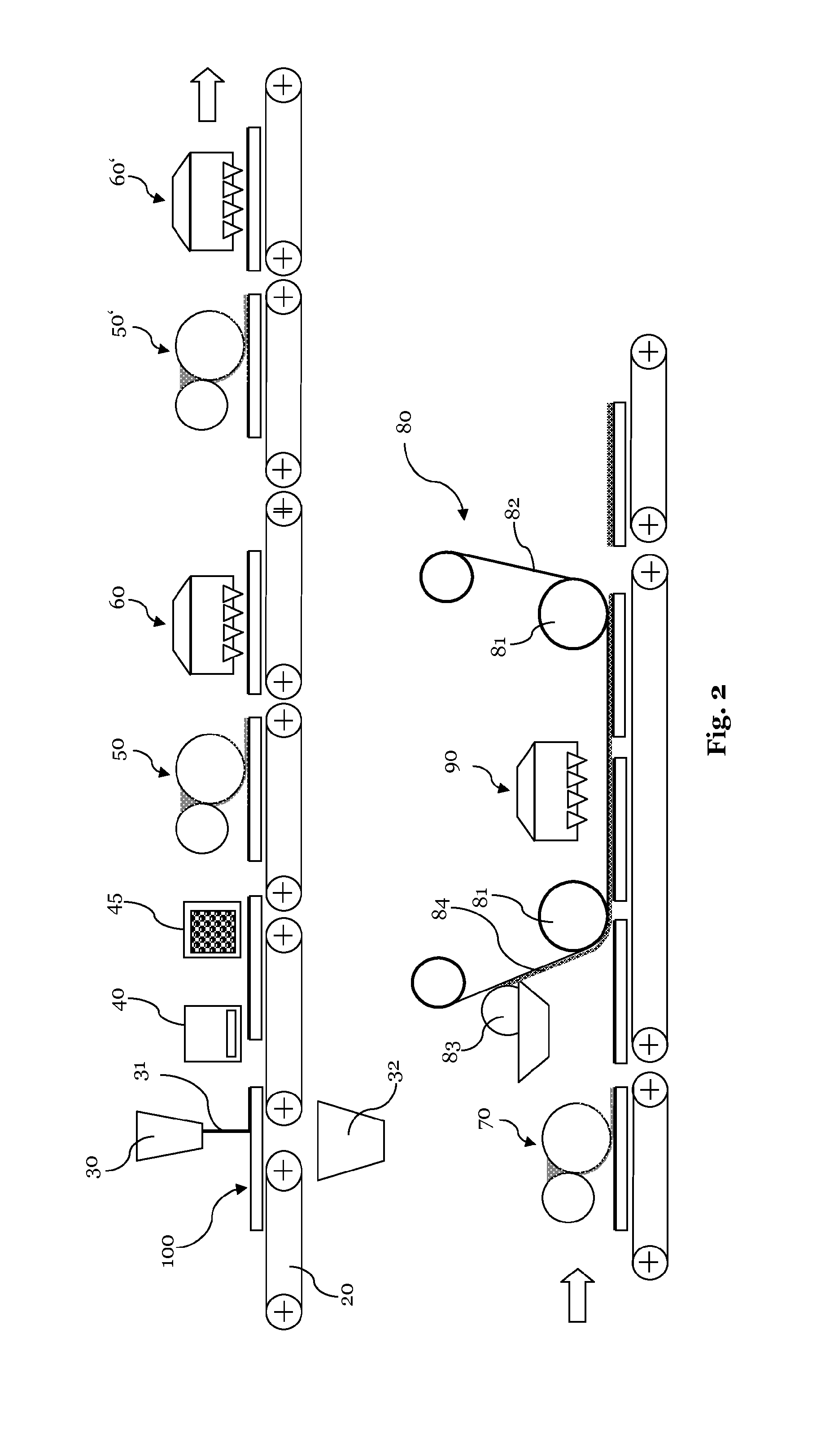
[0032]In a first step, an HDF-support plate with a thickness of 8 mm is provided with a primer by a roller application work based on a commercially available aqueous acrylic dispersion with an application of 10 g / m2. In a next step, the smoothing of the plate takes place by a roller application work by means of a filler (“Spachtelmasse”) based on a highly filled aqueous acrylic dispersion with an application amount of 25 g / m2. Subsequently, a printing ground (“Druckgrund”) (primer, “Grundierung”) is applied on the basis of an aqueous acrylate dispersion which is offset with fillers and color pigments by means of a casting method (“Gieβverfahren”) (i.e. a curtain coating method, “Vorhangbeschichtungsverfahren”) in an amount of 70 g / m2. After each of these coating steps an intermediate drying takes place at temperatures between 80 and 200° C. The thus treated plates are supplied to a printing machine essentially consisting of an engraved printing roller (“Gravurwalze”) and a rubber ro...

example 2

[0033]Panels, in which the printing image is generated by radiation-curing printing inks.

[0034]Again a 8 mm thick HDF-support plate is used and is provided with an aqueous primer, filler and printing base as described in example 1. The same decorative image is generated on the treated plate by means of a digital printer as described in example 1. Here, however, no dispersion colors are used, but UV radiation-curing digital printing inks. A color amount of about 2 g / m2 is required for the generation of the printing image. The color is initially fixed with 150 mJ / cm2 (mercury). Thereafter the application of 2 g / m2 of a commercially available UV-primer takes place. In this non-irradiated layer is a double bond-containing oligomer (1) provided with photoinitiators applied as in example 1 and this layer is cured together with the ink, i.e. polymerized by UV-radiation. Then the further layers are applied as in example 1. The resulting polymer layer comprises the printing ink and all layer...

example 3

[0035]An HDF-plate is subject to the production stages until after the printing machine as in example 1. A commercially available aqueous UV-primer is applied on the tried printing ink. The plate is heated by the upstream process with a surface temperature of 50-60° C. so that the water of the primer on the surface evaporates quickly and the primer is fixed. Subsequently, an oligomer mixture (1) as described in example 1 is applied in an amount of 50 g / m2 by means of a roller work and gelled by means of UV-radiation. Thereafter, a second roller application of 50 g / m2 of this oligomer mixture (1) takes place followed by gelling and finally a third application (1) of 50 g / m2 followed by gelling. Again, the same oligomer (1) is applied in an amount of 80 g / m2 by means of a further roller application work on this partially cured layer, which corresponds to the layer S1, and thereover the further layer is applied wet-on-wet by means of a film calender in an amount of 30 g / m2 and cured by...


PUM

PropertyMeasurementUnit
thicknessaaaaaaaaaa
thicknessaaaaaaaaaa
thicknessaaaaaaaaaa

Abstract

The present invention relates to a panel as well as a method for producing a panel, in particular a wall- ceiling- or floor panel. The method according to the invention provides that a layer of liquid radiation curing acrylate with a low Martens hardness is applied on a support layer in a first step. This is followed by an application of an intermediate layer in a second step and thereafter the application of a further layer wet-on-wet, which as a Martens hardness after curing which is larger than the Martens hardness of the first applied layer. The resulting panel has an intermediate layer with an inhomogeneous hardness profile due to the wet-on-wet application which leads to particularly advantageous properties.

Description

1. FIELD OF THE INVENTION[0001]The present invention relates to a panel as well as a method for producing such a panel, in particular a wall-, ceiling or floor panel with an improved surface coating.2. BACKGROUND OF THE INVENTION[0002]A plurality of panels for wall-, ceiling or floor coverings is known from the prior art. For example, so called laminate panels are widely used as floor coverings in indoor areas. The laminate panels are relatively inexpensive and can be processed well. They are usually applied on a support plate made of a MDF or HDF material, on top side of which a decorative paper, which is impregnated with a melamine resin, is applied. The resins are cured by pressing under the influence of heat and pressure, so that a highly abrasion-resistant surface is generated. Additionally, abrasion-resistant particles are often added to the surface before pressing, in particular corundum, for increasing the abrasion-resistance.[0003]As an alternative to laminate panels, panel...

Claims


Application Information

Patent Timeline
Patent Type & Authority Applications(United States)
IPC IPC(8): B41F19/00B05D3/06E04C2/38E04F15/02E04F15/10E04C2/34B05D7/00E04F13/08
CPCB41F19/001B05D7/587B05D7/584B05D3/067E04C2/38E04F13/0894E04F15/02038E04F15/107E04C2/34E04F13/0866B05D5/06B05D7/06B05D7/586E04F15/102B32B21/02B32B21/08B32B27/308B05D7/08
Inventor DOEHRING, DIETER
Owner XYLO TECH AG
Learn More