
Suction device/blower

a suction device and portable technology, applied in the direction of auxillary pretreatment, cleaning filter means, separation processes, etc., can solve the problems of uncomfortable electrostatic discharge between the collection bag and the operator, and achieve the effect of reducing or eliminating the potential difference between the collection bag and the atmosphere, flexible design, and easy folding and storag

Inactive Publication Date: 2007-10-09
ANDREAS STIHL AG & CO KG
View PDF11 Cites 18 Cited by
  • Summary
  • Abstract
  • Description
  • Claims
  • Application Information

AI Technical Summary

Benefits of technology

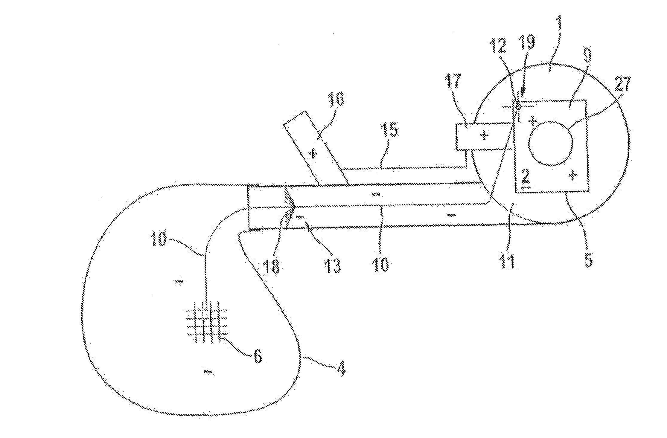
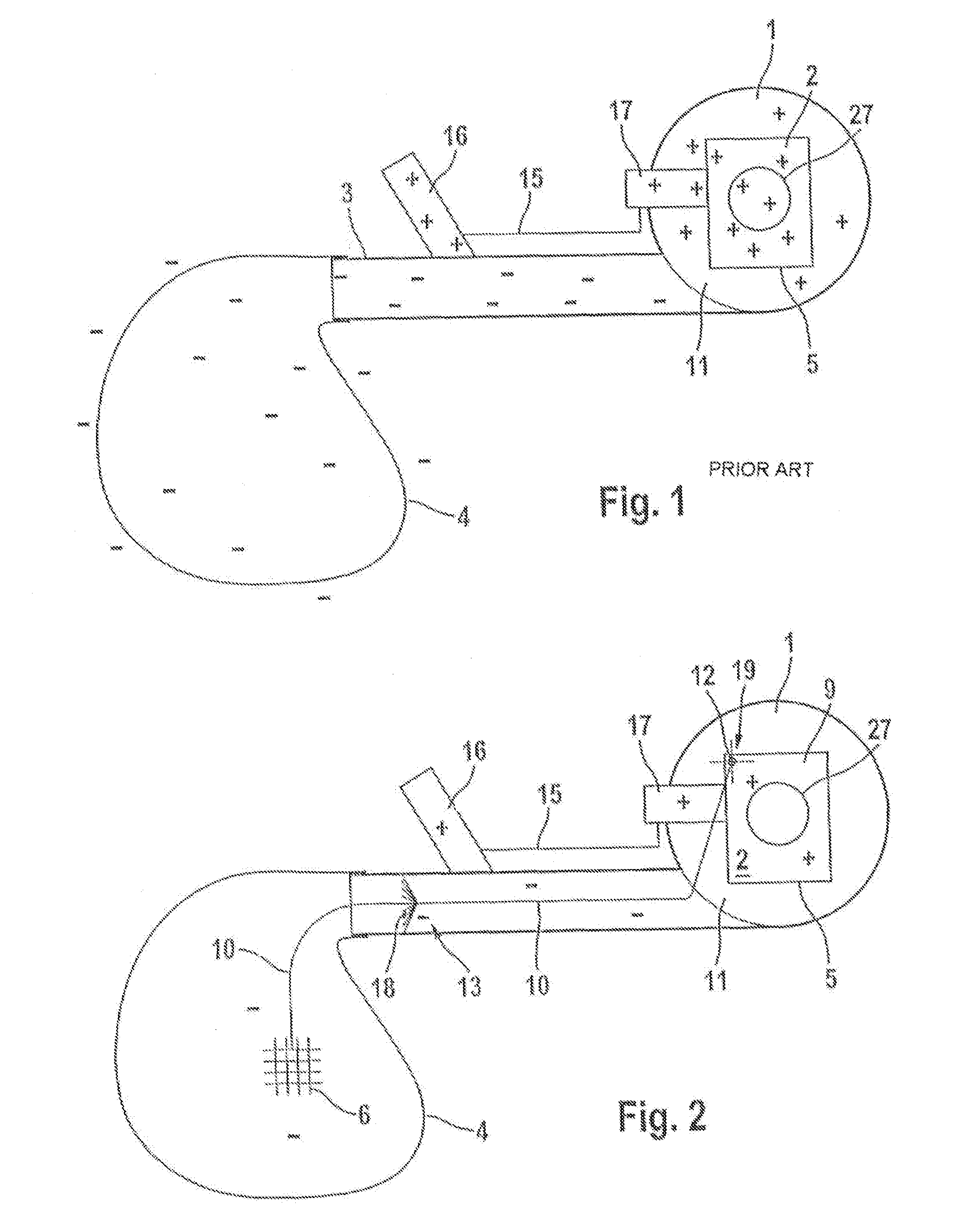
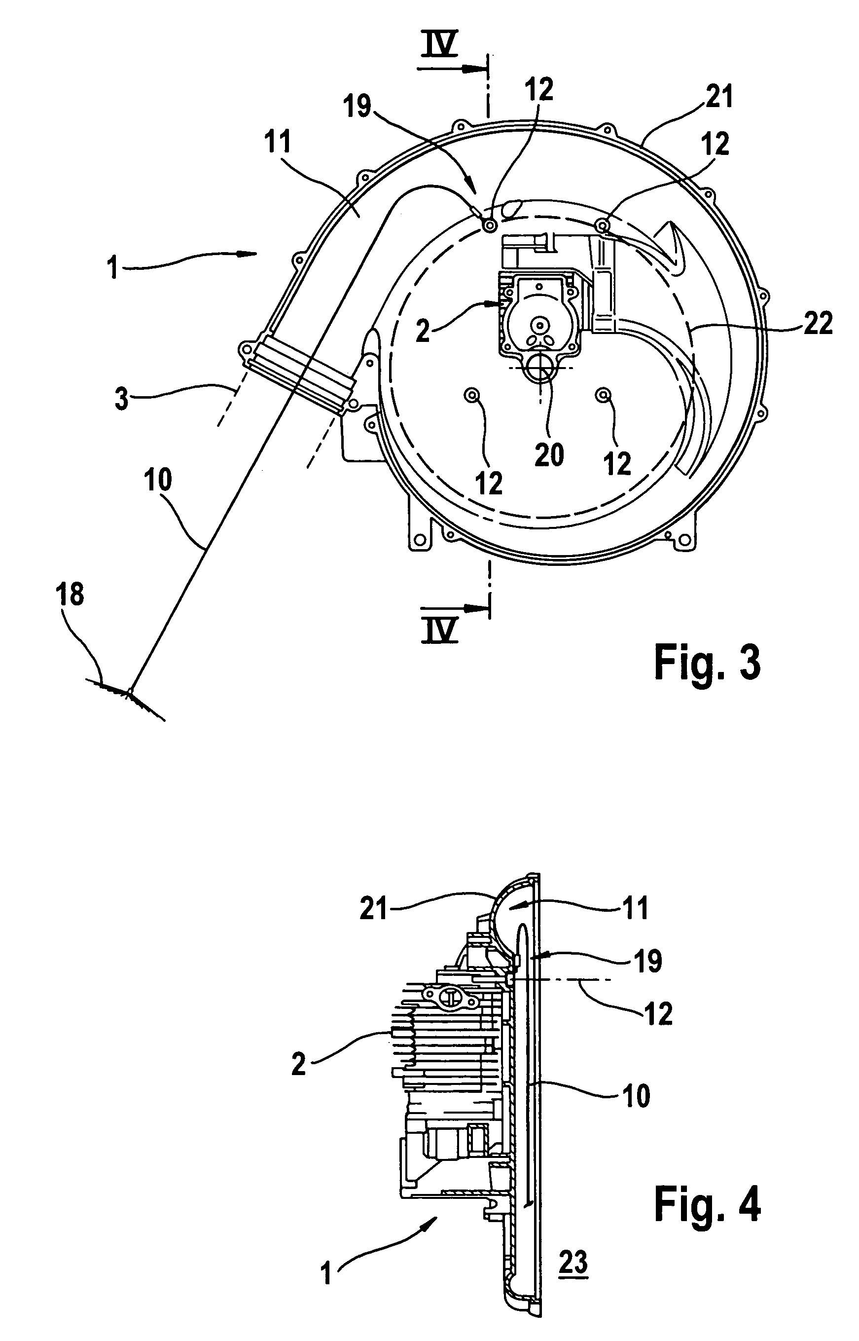
[0014]The suction device / blower of the present application comprises a potential-equalizing device that is disposed within the collection bag and is electrically conductively connected with an electrical ground connection of the suction device / blower. Dust particles, or other particles that are carried along in the air stream and during the course of the flow route are electrically charged, lead, when striking the inner surface of the collection bag, to the electrostatic charging thereof. By means of the electrical contacting of the potential-equalizing device of the collection bag with the electrical ground connection the resulting charge of the collection bag is shunted to ground. To a corresponding extent, the potential difference between the collection bag and the atmosphere is also reduced or eliminated. The collection bag can readily be contacted without this leading to an uncomfortable electrostatic discharge between the collection bag and the operator.
[0015]Pursuant to an advantageous further development, the potential-equalizing device has a flexible design. In particular in conjunction with a flexible collection bag, for example formed of a woven material, the shape can adapt to the air stream or the degree of filling of the collection bag without mechanically overstressing the bag. When not being used, the collection bag, along with the potential-equalizing device, can be easily folded and stored.
[0016]The potential-equalizing device is expediently embodied as an arrangement of electrically conductive, especially metallic, threads, whereby the collection bag is advantageously made of a woven material that includes the electrically conductive threads. As a consequence of the electrically conductive threads, the potential-equalizing device can have a flat and flexible configuration. A potential equalization can take place at any desired location of the collection bag. The formation of individual, insular locations not having potential-equalization is avoided. A woven material that includes the electrically conductive threads can have mechanical and electrical characteristics that are easily adapted to requirements. A thread or fiber fraction having greater mechanical resistance can be selected that while allowing a thin and lightweight configuration of the woven material provides an adequate load-carrying capacity. Any desired percentage of electrically conductive threads can be established as necessary for a reliable potential equalization. In particular, an embodiment of the woven material, or of the collection bag produced therefrom, is possible that entirely contains conductive fibers.

Problems solved by technology

The collection bag can readily be contacted without this leading to an uncomfortable electrostatic discharge between the collection bag and the operator.

Method used


Image

  • Suction device/blower
  • Suction device/blower
  • Suction device/blower

Examples


Embodiment Construction

[0022]Referring now to the drawings in detail, FIG. 1, in a schematic block diagram, shows the essential components of a manually-guided, portable suction device / blower pursuant to the state of the art. The blower has a blower or fan unit 1, which is driven by a motor 2. In the illustrated embodiment, the motor 2 is an internal combustion engine having an indicated carburetor 17. An electric motor or the like can also be provided. The blower unit 1 is provided with a discharge elbow 11 which is followed by a discharge or blower tube 3 that continues from the blower unit 1. The free end of the blower tube 3 opens into a collection bag 4. By means of a central suction or intake opening 27 of the blower unit 1, and a non-illustrated intake tube connected thereto, an air stream can be drawn in and conveyed via the blower tube 3 into the collection bag 4.

[0023]A handle 16 having control elements for the motor 2 is mounted on the outside of the blower tube 3. From the control elements on ...


PUM

PropertyMeasurementUnit
flexibleaaaaaaaaaa
electrically conductiveaaaaaaaaaa
electricallyaaaaaaaaaa

Abstract

A manually-guided, portable suction device / blower is provided, and includes a blower unit having a motor for driving the blower unit, a blower tube that extends from the blower unit, a collection bag, wherein during suction operation of the suction device / blower, the blower tube opens out into the collection bag, and a potential-equalizing device disposed within the collection bag, wherein the potential-equalizing device is electrically conductively connected with an electrical ground connection of the suction device / blower.

Description

BACKGROUND OF THE INVENTION[0001]The present invention relates to a manually-guided, portable suction device / blower.[0002]With manually-guided, portable suction devices / blowers, an air stream is produced by means of a motor-driven blower unit. By means of a suction or vacuum tube that is connected, for example, on the suction side of the suction device / blower, dust, leaves or the like can be sucked up from the ground and blown into a collection bag via a blower tube that is disposed on the discharge side.[0003]Embodiments are also known where an underpressure device, for example in the form of a venturi device, which is actuated by the air stream, is disposed in the blower tube. In this connection, a suction tube opens out into the venturi device. Matter can be drawn in through the suction tube and the venturi device and can be conveyed further via the blower tube to the collection bag, without having to pass the blower unit that drives the air stream. Such arrangements are used in ...

Claims


Application Information

Patent Timeline
Patent Type & Authority Patents(United States)
IPC IPC(8): B01D29/11A47L5/14A47L9/14A47L9/28H05F3/02
CPCA47L5/14A47L9/14A47L9/2889A01G1/125H05F3/02Y10S55/45Y10S55/02A01G20/47
Inventor HABERLEIN, JURGEN
Owner ANDREAS STIHL AG & CO KG
Learn More