
Voltage converting circuit and battery device

a voltage conversion circuit and battery technology, applied in secondary cell servicing/maintenance, process and machine control, instruments, etc., can solve the problems of battery aging, battery aging, battery aging, etc., and achieve the effect of reducing the size and weight of these batteries, reducing the characteristics of lithium-ion secondary batteries and other high-performance batteries

Active Publication Date: 2009-07-28
TEXAS INSTR INC
View PDF4 Cites 19 Cited by
  • Summary
  • Abstract
  • Description
  • Claims
  • Application Information

AI Technical Summary

Benefits of technology

The present invention is a voltage converting circuit that converts the voltage of multiple power storage devices into a constant voltage using a predetermined potential as a reference. The circuit includes a selection circuit that connects one power storage device to the output node pair, and a sampling circuit that samples the voltage of the output node pair using a predetermined potential. The selection circuit includes switch circuits that connect the power storage devices to the output nodes, and a drive circuit that generates a drive current based on the potential of the selected power storage device. The drive circuit includes a drive current generating circuit and a voltage generating element that generates a drive voltage based on the drive current. The circuit ensures that the breakdown voltage of the driving input of the switch circuit remains constant even if the potential of the selected power storage device becomes high. The circuit can be used in a variety of applications where the voltage of the power storage device needs to be converted.

Problems solved by technology

As a result, the size and weight of these batteries has been reduced, and the batteries can drive devices for a long time.
On the other hand, the characteristics of lithium-ion secondary batteries and other high-performance batteries tend to deteriorate when the cell voltage becomes excessively high due to overcharging or extremely low due to over-discharging or when an excessively large charging current flows through the cell, which creates problems.
In order to increase the gate-source breakdown voltage, it is necessary to adopt an appropriate design and manufacturing process for the MOS transistors, which may create problems in terms of manufacturing cost or element surface area.
On the other hand, since the number of the series connected cells is increased and the voltage is raised, the error becomes large when converting the potential of the cell selected by the selector circuit to the ground level of the measurement system.
However, since high accuracy is required for the resistance as the potential of the cell of the measurement object is increased, it is difficult to measure the voltage accurately.
However, since the parasitic capacitance of the transistor that constitutes the switch becomes the error of the measurement, the electrostatic capacitance of the capacitor must be much higher than said parasitic capacitance.

Method used


Image

  • Voltage converting circuit and battery device
  • Voltage converting circuit and battery device
  • Voltage converting circuit and battery device

Examples


Embodiment Construction

[0059]In the following, an embodiment of the present invention will be explained based on the figures.

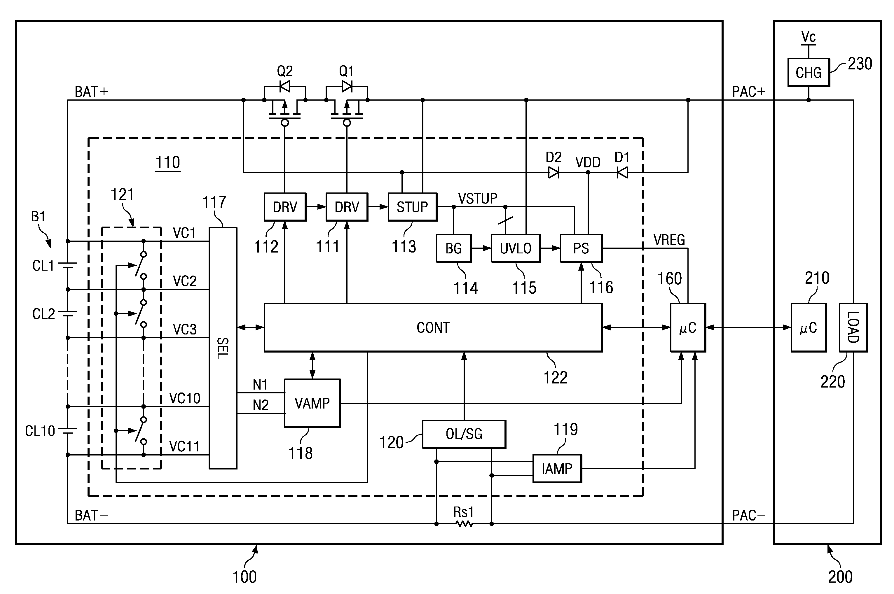
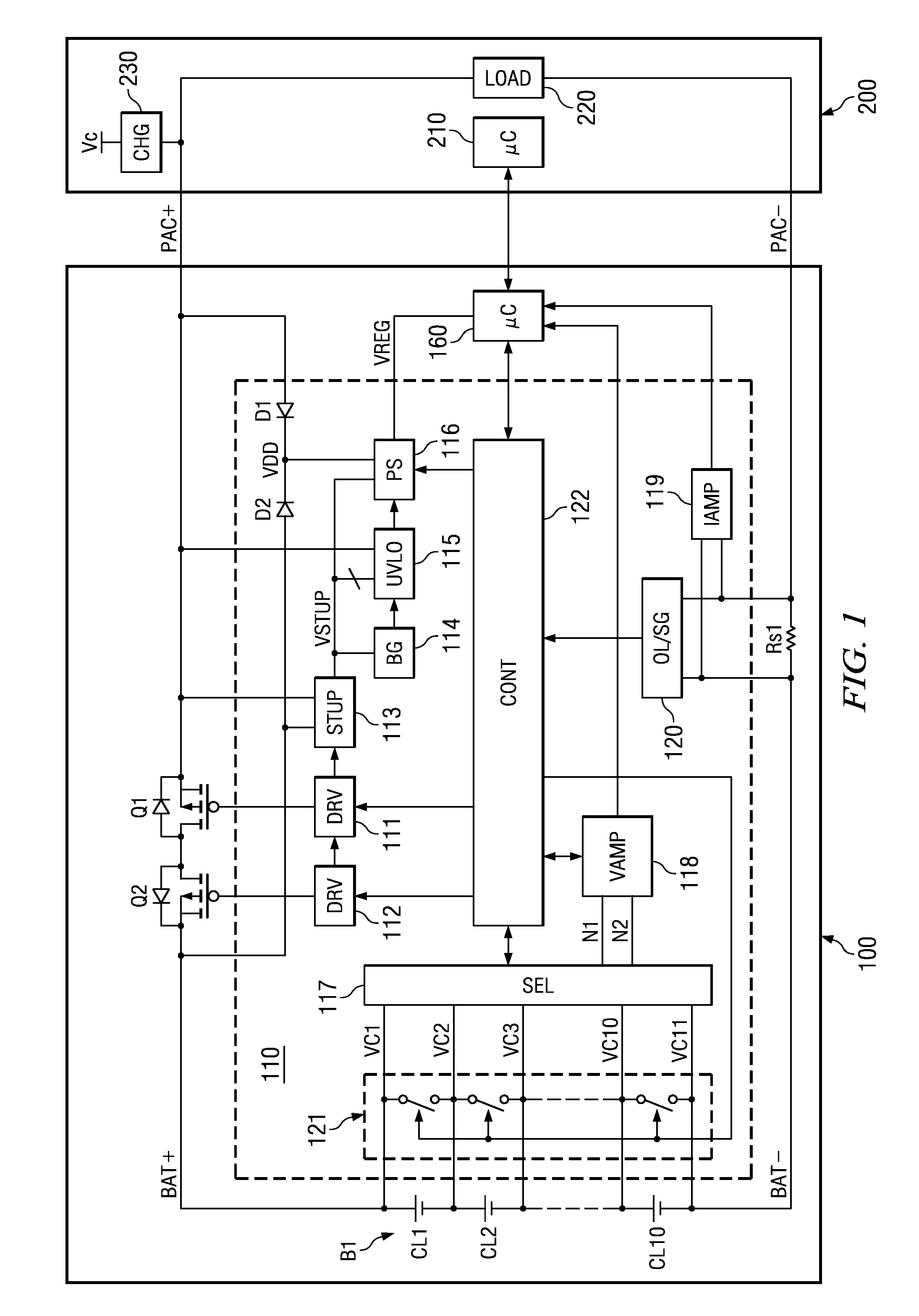
[0060]FIG. 1 is a diagram illustrating a configuration example of the battery device disclosed in the embodiment of the present invention.

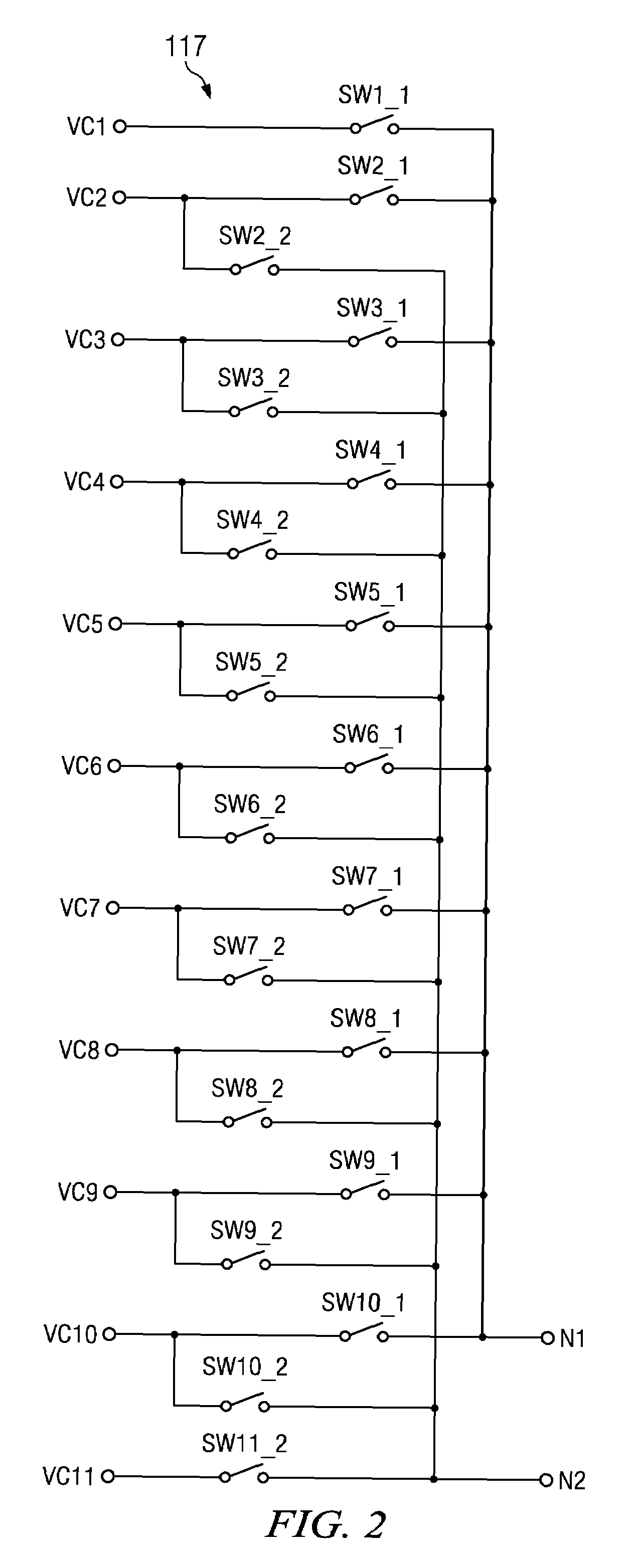
[0061]Battery device 100 shown in FIG. 1 has p-type MOS transistors Q1, Q2, battery B1, resistor Rs1 for current detection, analog front end part (AFE part) 110, and microcomputer 160. AFE part 110 includes diodes D1, D2, drive circuits 111, 112 of MOS transistors Q1, Q2, setup circuit 113, reference voltage generating circuit 114, low-voltage operation lock circuit 115, power supply circuit 116, selection circuit 117, voltage amplification circuit 118, current amplification circuit 119, overcurrent / short circuit detection circuit 120, current bypass circuit 121, and control circuit 122.

[0062]The circuit block including selection circuit 117 and voltage amplification circuit 118 is an example of the voltage converting circuit of the present invent...


PUM


Abstract

A voltage converting circuit and a battery device, aimed at the problem that the breakdown voltage required for the driving input of the selected switch element is increased as the potential of the selected power storage device is increased when a power storage device is selected from a plurality of power storage devices that are connected in series. A certain drive voltage for turning on p-type MOS transistors Q3, Q4 of selection circuit 121 is generated based on a certain drive current Ion flowing from one power storage element to ground level GND. In other words, even if the power storage device selected by selection circuit 121 has a high potential with respect to ground level GND, the drive voltage applied between the gate and source of MOS transistors Q3, Q4 can be held substantially constant.

Description

FIELD OF THE INVENTION[0001]The present invention pertains to a voltage converting circuit that converts the voltage of each of several series connected power storage devices into a voltage using a prescribed potential as a reference, for example, a voltage converting circuit that converts the voltage of each of several series connected battery cells in a battery device into the voltage of ground level in order to measure the voltage of each battery cell.BACKGROUND OF THE INVENTION[0002]In recent years, the energy density of lithium-ion secondary batteries, nickel-hydrogen secondary batteries, and other types of batteries has been significantly increased. As a result, the size and weight of these batteries has been reduced, and the batteries can drive devices for a long time. The improvement performance of these batteries has greatly contributed to the popularization of cellular phones and other portable electronic devices.[0003]Accompanying the improved battery performance is the i...

Claims


Application Information

Patent Timeline
Patent Type & Authority Patents(United States)
IPC IPC(8): G05F1/10H02J7/02
CPCH01M10/425H01M10/482H01M10/46H01M10/441G01R31/3658G01R31/396Y02E60/10
Inventor YOSHIO, KATSURA
Owner TEXAS INSTR INC
Learn More