
Method for treating oil sands and device for implementing such a method

Inactive Publication Date: 2016-04-21
TOTAL PUTEAUX FR +1
View PDF1 Cites 4 Cited by
  • Summary
  • Abstract
  • Description
  • Claims
  • Application Information

AI Technical Summary

Benefits of technology

The present invention aims to provide a method for treating oil sands that can maximize the recovery of bitumen and produce a clean sand free from bitumen. This method should be simple to implement, efficient, and not require expensive and difficult techniques such as deasphalting using heavy solvents, grinding and fine sieving, or centrifugation.

Problems solved by technology

These washing operations consume a lot of water, which has a considerable ecological impact despite the considerable use of water recycling, since the used water is discharged and held in tailings ponds, which is intended to purify the water prior to its discharge to the environment.
These conventional techniques pose major environmental problems.
Thus, problems of water resources, large-scale lagooning of wastewaters and general degradation of biodiversity call into question the exploitation of oil sands by the conventional techniques of strip mining.
A major drawback of the technique developed by Welmers et al. is that, although the bitumen recovery rate is about 90%, the extraction results are limited in performance.
The practical benefit of this method is limited, in that it consists firstly of agglomerating oil sand, and then grinding the agglomerates obtained, which constitutes two unit operations with mutually opposing purposes, both of which are expensive in energy and equipment.
Said method is characterized by great complexity, which is necessarily a source of various malfunctions, and consequently involves high costs in terms of application, for example connected with high energy consumption and with probable deficiencies of operational reliability.
Moreover, handling of dry, combustible powders presents severe risks in terms of industrial safety.
On the one hand, enrichment by cryogenic grinding carried out by these methods is unable to give a mineral-free bitumen with a satisfactory yield of material and satisfactory energy efficiency, which necessitates employing subsequent treatments to obtain a hydrocarbon phase free from mineral compounds.
Moreover, it is known that the techniques of cryogenic grinding are very sensitive to the nature of the oil sand treated.
In fact, these techniques offer very limited reliability owing to the variations of the materials of mining origin to be treated, notably the variations in composition and mechanical, rheological or physicochemical behavior, connected with the site and with the conditions of mining exploitation employed.
It is also known that the operations described in these three patents (grinding and fine sieving, zigzag impactors, induced vortex separator, cyclones in cascades, filters or electrostatic separators) are not suited to ore treatment capacities with very high tonnage and are only carried out industrially to produce small tonnages of very clean (nonsticky) products with high added value.
Despite its complexity, this method has limited performance since, according to the example in U.S. Pat. No. 3,993,555, the recovery rate is only 91%.
Moreover, its energy consumption is considerable owing to the large amounts of solvent used.
In addition, it has the major drawback of using an organic solvent that is potentially harmful and ecotoxic, which greatly limits the interest in the method.
Such a method is undeniably complex: the whole of the method is carried out at low temperature, employs three deasphalting units, a cryogenic coarse grinding mill, a sieving step, filtration steps with at least three large-capacity filters, and uses two paraffinic solvents, which must be recovered and recycled.
This results in a very expensive method, both in capital investment and in terms of energy, and whose performance in carbon yield relative to the bitumen of the oil sand is unsatisfactory.
Therefore the technologies for extracting bitumen from oil sands described above do not lead to satisfactory results, in terms of bitumen recovery rate, or in terms of cost and industrial operability of the method.

Method used


Image

  • Method for treating oil sands and device for implementing such a method
  • Method for treating oil sands and device for implementing such a method
  • Method for treating oil sands and device for implementing such a method

Examples


example 1

The Case of Cryogenic Grinding and Sieving Cooled Conventionally and without Addition of Separating Fluid

[0142]This example makes it possible to verify that cryogenic grinding and sieving without addition of separating fluid only leads to a method of treatment with limited performance.

[0143]The work was carried out with an oil sand that contained 0.4% of water and, after drying, contained 11 wt % of bitumen and 89% of mineral material. Various samples of this oil sand were submitted to an operation of cryogenic grinding and sieving. For this purpose, the work was carried out in an air-conditioned room at −25° C. and all the instruments used during the experiments that were carried out: grinding mill, sieve, tweezers, spatulas, etc., were cooled beforehand with liquid nitrogen.

[0144]The grinding mill used was of the rotary impact type made by the company Fritsch, of the “Pulverisette 14.702” type. The rotary speed of the grinding mill was maintained at 15 000 revolutions per minute.

[...

example 2

The Case of Cryogenic Grinding and Sieving Cooled with Solid or Liquid CO2 but without the Presence of a Separating Fluid

[0150]In this case, the nature of the oil sand submitted to the experiment is the same as previously, i.e. containing, after drying, 11% of bitumen and 89% of inorganic material. The grinding mill is also of the Fritsch rotary type, “Pulverisette 14702”.

[0151]But this time, instead of permanently cooling the laboratory to −25° C. and the equipment temporarily with liquid nitrogen, the grinding mill was put in an atmosphere cooled by supplying an initial weight of solid CO2 and purging with gaseous CO2, also cooled. The temperature of the grinding mill during operation could thus be maintained at about −30° C. As soon as grinding was finished, the resultant oil sand was recovered in an atmosphere consisting of gaseous CO2 resulting from the change of state of the solid CO2 initially introduced to cold gaseous CO2 and liquid CO2, which itself transformed into gaseou...

example 3

Extraction According to the Invention

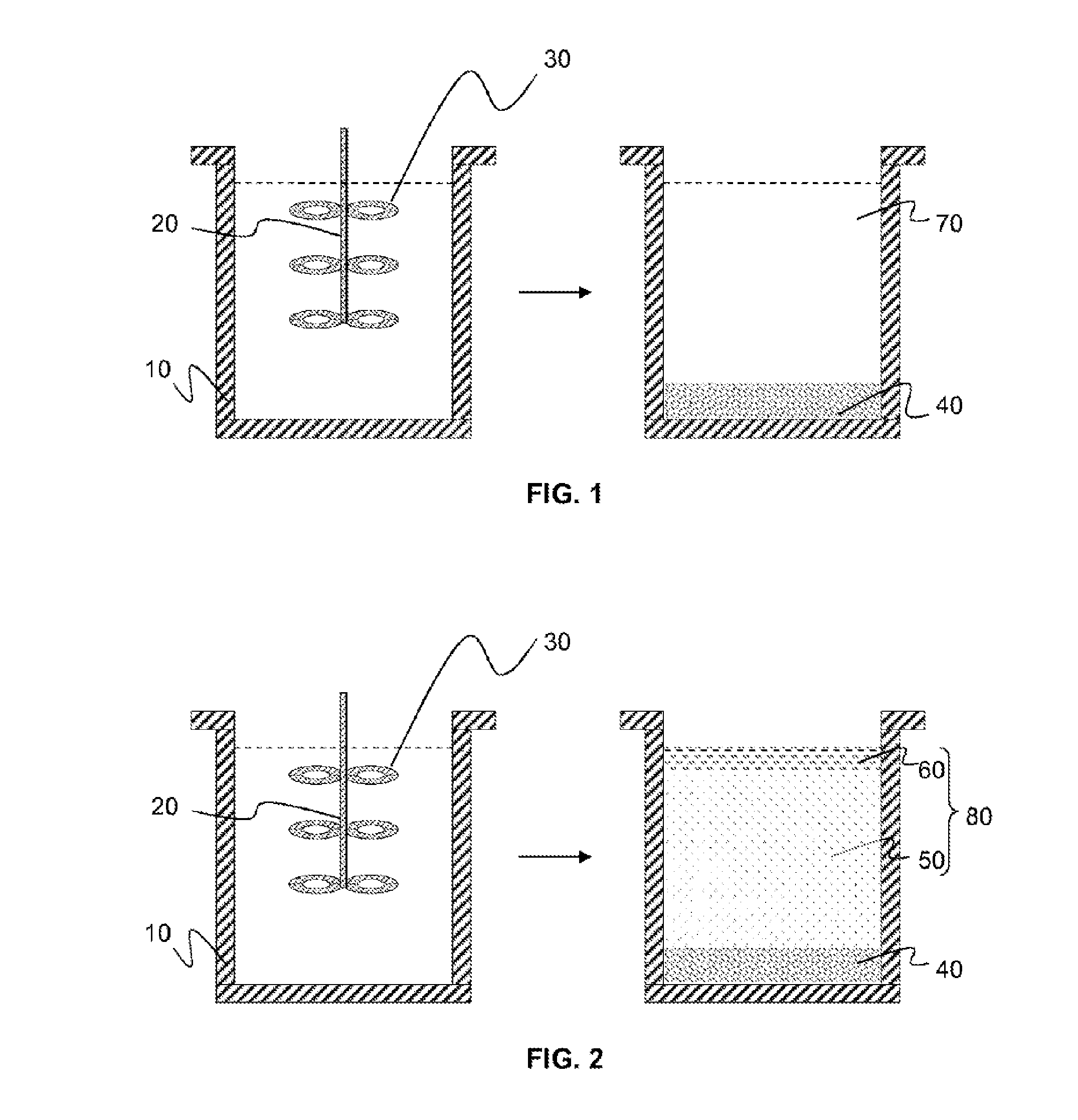
[0155]Learning from the unsatisfactory results of examples 1 and 2, we tried to reproduce experimentally the method according to the invention on laboratory equipment used conventionally for visualization of thermodynamic equilibria at high pressure, consisting of a transparent cell of about 50 cm3 (sapphire tube with height of 100 mm and inside diameter of 25 mm) placed in an enclosure that could maintain the temperature of the cell at a fixed value by controlled injection and expansion of carbon dioxide. A stirring rotor with a vertical axis is arranged at the bottom of the cell. An external system makes it possible to circulate the fluid (CO2) through the cell and adjust the pressure to a fixed value.

[0156]Three types of oil sands (OS) were employed. The composition of these oil sands is shown in Table 3 below (in wt %):

TABLE 3Sample% Bitumen% Water% Mineral matterOS A12.45.582.1OS B9.15.885.1OS C5.911.382.8

[0157]The test sample (15 g) and pel...


PUM


Abstract

The invention relates to a method for treating oil sand. The steps consisting of cooling said oil sand to a temperature lower than the glass transition temperature of the bitumen by bringing said oil sand into contact with carbon dioxide in the solid state and applying mechanical energy to the mixture produced. Then melting the solid carbon dioxide in such a way as to produce a multiphase system. The multiphase system is then separated into at least one solid phase and at least one liquid phase. The bituminous phase is then recovered from the separated liquid phase. The invention also relates to a device for treating oil sand, especially designed for implementing said method.

Description

RELATED APPLICATIONS[0001]The present application is a National Phase entry of PCT Application No. PCT / FR2014 / 051179, filed May 20, 2014, which claims priority from FR Patent Application No. 13 54658, filed May 23, 2013, said applications being hereby incorporated by reference herein in their entirety.FIELD OF THE INVENTION[0002]The field of the invention is the treatment of oil sands. The invention relates in particular to a method for treating oil sands using carbon dioxide firstly in solid form and then in liquid form. The invention also relates to devices for implementing such a method.BACKGROUND OF THE INVENTION[0003]Oil sands (also called “tar sands” or “bituminous sands”) are hydrocarbon reserves consisting of a mixture of heavy oils degraded to bitumens and inorganic matter. Typically, oil sand has a bitumen content in the range from 5% to 20% (by weight). The inorganic matter essentially consists of sand, but it may also contain other mineral compounds, such as clays, and w...

Claims


Application Information

Patent Timeline
IPC IPC(8): C10G1/04B03B9/02C01B32/40
CPCB03B9/02C10G1/045C10G1/00C10G2300/4006B03B1/00
Inventor HALAIS, CHRISTOPHEBOUSQUET, JACQUESPERRUT, MICHEL JEAN BAPTISTE,
Owner TOTAL PUTEAUX FR
Learn More