
System for fixing a lamp to a headlight lamp holder for an automobile

Inactive Publication Date: 2006-07-13
VALEO VISION SA
View PDF10 Cites 16 Cited by
  • Summary
  • Abstract
  • Description
  • Claims
  • Application Information

AI Technical Summary

Benefits of technology

[0008] The aim of the invention is precisely to resolve the drawbacks of the techniques disclosed above by providing an improved fixing system for a D1 lamp and D2 lamp and which will in particular not dismantle and / or is more simple to implement. This fixing system makes it possible to hold and lock the discharge bulb with the lamp holder. For this purpose, the invention uses the assembly of a non-removable flexible annulus on the lamp holder of the headlight and a rigid ring able to move with respect to the flexible annulus.

Problems solved by technology

Changing this bulb and high-voltage module assembly is relatively tricky because firstly of the difficulty of access to the D1 lamp and the operations to be performed for removing the faulty assembly and installing the new assembly and secondly because of the risks due to the high voltage present in the module.
However, changing a bulb in a D2 lamp is even more tricky than changing the bulb and module assembly for a D1 lamp.
This is because, in a headlamp, which is difficult of access, the user must first of all remove the module and remove the bulb; he must then change the bulb and replace the module on the bulb, with all the risks inherent in the high voltage in the module.
However, as explained before, the environment of a lamp and a reflector is relatively small, which makes these rotation movements difficult and tiring for the user to perform.
However, a vehicle in operation vibrates.
The vibrations of this vehicle can give rise to a progressive unscrewing of the ring and consequently undesirable dismantling of the lamp.
However, the closure of such a spring blade system requires an additional movement on the part of the user, which complicates further the bulb changing by the user.
In addition, the actuation of such a spring blade gives rise to a relatively high movement, inappropriate for a small environment such as that of a headlight.

Method used


Image

  • System for fixing a lamp to a headlight lamp holder for an automobile
  • System for fixing a lamp to a headlight lamp holder for an automobile
  • System for fixing a lamp to a headlight lamp holder for an automobile

Examples


Embodiment Construction

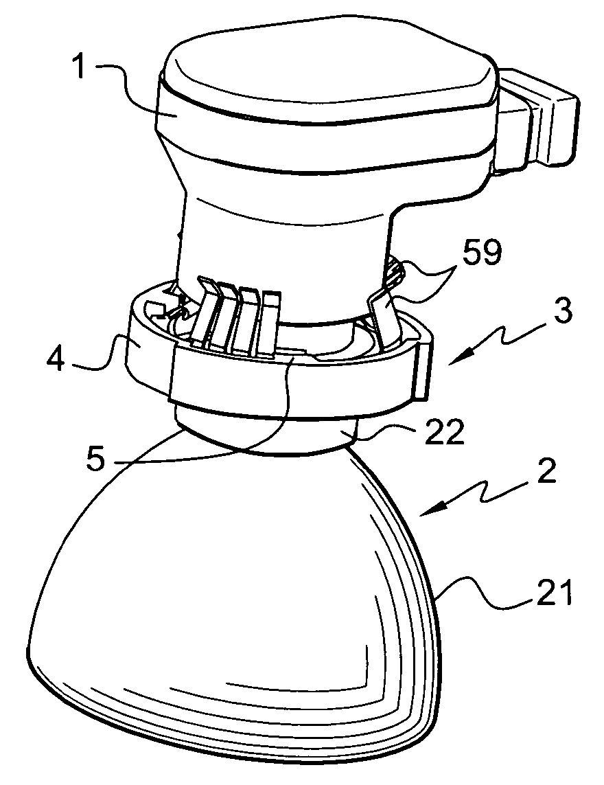
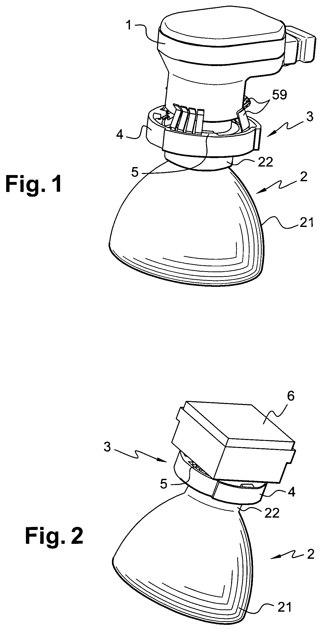
[0038]FIG. 1 depicts a fixing system according to the invention mounted around a D2 light source. This figure shows a lamp 1 mounted on a mating part 2 of the headlight by means of a fixing system 3. The mating part 2 is the part of the headlight comprising a reflector 21 and a lamp holder 22. In some embodiments of the headlight, the lamp holder 22 and the reflector 21 form, together, one and the same piece 2. The lamp holder may also not be an integral part of the reflector 21; in this case, it is only fixed to the reflector at the time of assembly of the headlight.

[0039] The role of the lamp holder 22, for example cylindrical in shape, is to support the discharge bulb of the lamp 1. It also centers and orients the bulb inside the reflector 21. The fixing system 3 of the invention is mounted around this lamp holder 22.

[0040] As can be seen in FIG. 1, the fixing system 3 comprises a rigid ring 4 and a flexible annulus 5 assembled so that the rigid ring is able to move with respec...


PUM


Abstract

A lighting and / or signaling device for an automobile comprising a xenon lamp and a mating part comprising a reflector and a lamp holder providing the holding of a bulb of the discharge lamp in front of the reflector. A system for fixing the xenon lamp on the mating part comprising a rigid ring able to be mounted, so as to be able to move in rotation, about the lamp holder and a flexible annulus mounted inside the rigid ring and fixed to the lamp holder so as to be non-removable.

Description

FIELD OF THE INVENTION [0001] The invention concerns a system for fixing a lamp of the discharge-lamp type, also referred to as a xenon lamp, on a lamp holder of a lighting and / or signaling device, of the headlight type, for an automobile. The invention finds applications in the automobile field, and more precisely in the field of automobile lighting. Its aim is in particular to develop a rapid fixing for a discharge lamp with the possibility of interchangeability between various models of discharge lamp. STATE OF THE ART [0002] Currently, lighting devices are provided with light sources which can be of various kinds. In particular, vehicle headlights can be equipped with several light sources, which may be of two different kinds, for example: a halogen lamp and a discharge lamp. In the case of a discharge lamp, the light source is equipped with a high-voltage module which provides the electrical supply to the bulb of the discharge. [0003] Amongst discharge lamps, there exist severa...

Claims


Application Information

Patent Timeline
IPC IPC(8): F21V1/00F21W107/10
CPCF21S48/1104F21S48/1109F21S48/1186F21V25/00F21S41/172F21S41/19F21S41/192
Inventor JOSQUIN, DANIELMASSE, JEAN
Owner VALEO VISION SA
Learn More