
Data storage

Inactive Publication Date: 2003-02-06
HEWLETT-PACKARD ENTERPRISE DEV LP
View PDF0 Cites 17 Cited by
  • Summary
  • Abstract
  • Description
  • Claims
  • Application Information

AI Technical Summary

Benefits of technology

[0009] Relying on the information held in the non-user data is advantageous because it can provide a more robust approach and therefore, is it less likely that data will be lost.
[0015] The reader may comprise a plurality of read-heads, each of which is arranged to read a separate channel of data, preferably in parallel with one another. In the preferred embodiment the reader comprises 8 read heads, although the reader could comprise any number of read heads. For example the reader may comprise 2, 3, 4, 5, 6, 7, 9, 10, 11, 12, 13, 14, or more read heads. An advantage of providing more than one read head in this manner is that the rate at which data can be read from the data-holding medium is increased.
[0024] The method may comprise monitoring the identity of the datasets being read from the data-holding medium and determining if more than two datasets have occurred within the overlap zone. It is possible for data from two datasets to occur within the overlap zone, this occurs if at least one set of data is re-written after writing of a second dataset has started. However, if a third dataset occurs in this region it is likely that an error occurs and therefore, it is advantageous to monitor the data-holding medium for such an occurrence.
[0030] Conveniently the method comprises using the non-user data to determine if any of the sets of data from a dataset have been re-written and restarting the timing if any re-writes are detected once the last set of user data within a dataset has been read. Such a method is advantageous because if any of the sets of data have been re-written, these re-writes may themselves be re-written, which extends the period in which re-writes occur.
[0037] The method may comprise using a state machine to monitor the zone into which data being read from the data-holding medium falls. An advantage of using a state machine in this manner is that is that it provides a convenient structure to track the zone.
[0041] An advantage of such a data reader is that by not detecting the first marker can make the data reader simpler to implement. As such it may be easier to configure, and may be more reliable. Reliability is an important consideration for certain applications in which a data reader may be used (for example in data backup applications, in which data recovery and reliability are important issues).

Problems solved by technology

In view of the amount of information other than user data that is held on the data-holding medium, this can be problematic,
A problem with detecting the marker in this manner is that if the marker is not detected, or data is interpreted as the marker, then data can be lost.
Further, when data is written to the data-holding medium it may overwrite data already in existence on the data-holding medium.
However, there may be a latency between a dataset finishing on the data-holding medium and the stat of the over written data, which can result in a portion of data from a dataset that should have been over written remaining.
In such marker detecting methods, user data can be lost if the marker is missed by the reader, the marker becomes damaged and is therefore not intelligible, or data is mis-interpreted as a marker.
However, if a third dataset occurs in this region it is likely that an error occurs and therefore, it is advantageous to monitor the data-holding medium for such an occurrence.
Due to latencies within the writing apparatus used to rite data to the data-holding medium such re-writes may well occur after the last set of data within a dataset.
Prior methods have relied upon detecting markers on the data-holding medium, which can be problematic if the marker is corrupted in any manner, or missed.
Further, when data is written to the data-holding medium it may overwrite data already in existence on the data-holding medium.
However, there may be a latency between a dataset finishing on the data-holding medium and the start of the overwritten data, which can result in a portion of data from a dataset that should have been over written remaining.

Method used


Image

  • Data storage
  • Data storage
  • Data storage

Examples


Embodiment Construction

with reference to the accompanying Figures of which:

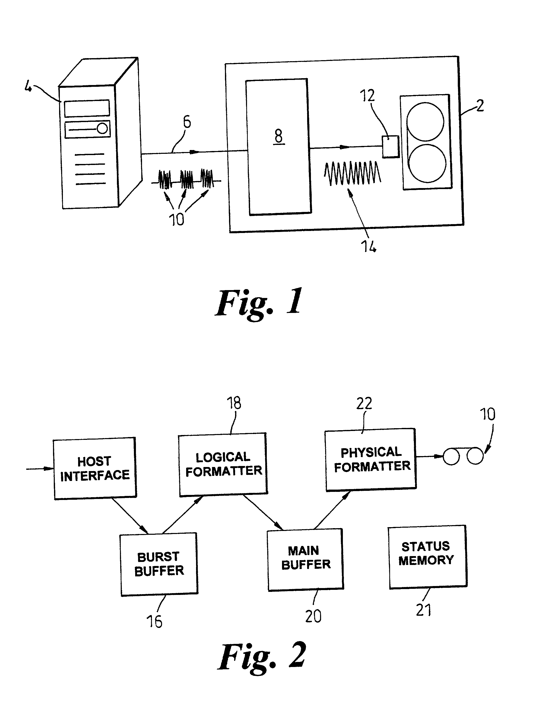
[0043] FIG. 1 is a schematic diagram of a computer connected to a tape drive according to the present invention;

[0044] FIG. 2 is a schematic diagram of the tape drive shown in FIG. 1, showing the main components thereof;

[0045] FIG. 3 shows the structure into which data received by the tape drive is arranged;

[0046] FIG. 4 shows further detail of the data structure of FIG. 3 and how the data contained therein is written to a tape;

[0047] FIG. 5 shows further detail of a portion of the data structure shown in FIGS. 3 and 4, and shows the physical arrangement of the dataset on the tape;

[0048] FIG. 6 shows how data is written on a tape inserted into the tape drive of FIG. 1;

[0049] FIG. 7 shows more detail of how data is written to tape;

[0050] FIG. 8 shows yet further detail of how data is written to the tape;

[0051] FIG. 9 shows how neighboring data blocks can be arranged on a tape, after read while write retries have occurred;

[0052] FIGS...


PUM


Abstract

A data reader arranged to read a data-holding medium 10 containing both user 30 and non-user 32, 34 data, said non-user data 32, 34 holding information relating to said user data 30, said data reader comprising at least one read head 12 arranged to read the data-holding medium 10 and generate a data signal 14 comprising user data and non-user data, said user data being arranged into a plurality of sets interspersed with said non-user data, said non-user data being arranged to identify said user data within said sets, processing circuitry 8 being arranged to receive and process said data signal 14 and obtain said user data 30 from said data signal 14 using said non-user data 32, 34 to identify said user data 30 within said data signal 14. The data reader is particularly suitable for use in tape drives, and / or in situations in which re-writes, and overwrites of data occur.

Description

[0001] This invention provides an improved data reader suitable for a data storage device, which may be a tape drive arranged to receive data from a computer, or the like. The invention also provides related methods and devices incorporating such a reader,BACKGROUND AND OBJECTIVES[0002] An example of a data storage device is the tape drive, which receive user data from computers, particularly, but not exclusively to back-up the user data held on the computer onto a data-holding medium. In such back-up applications it is of prime importance that the user data is retrievable, since generally, this copy is the back-up copy that will only be required if the original copy has been lost or damaged Therefore, there is an ongoing need to ensure that backup data storage devices are as robust and secure as possible.[0003] Once user data has been stored on the data-holding medium it can be held there for long periods. To recover the user data from the data-holding medium the data storage devic...

Claims


Application Information

Patent Timeline
IPC IPC(8): G06F3/06G11B20/12G11B27/30G11B27/36
CPCG06F3/0682G11B20/1209G11B27/3027G11B27/36G11B2020/10898G11B2220/213G11B2220/216G11B2220/218G11B2220/2512G11B2220/2525G11B2220/2545G11B2220/2562G11B2220/2575G11B2220/90G11B2220/913
Inventor BUCKINGHAM, JONATHAN PETER
Owner HEWLETT-PACKARD ENTERPRISE DEV LP
Learn More