Eureka AIR delivers breakthrough ideas for toughest innovation challenges, trusted by R&D personnel around the world.

Method for producing a composite material with a carbide matrix

a technology of carbide matrix and composite material, applied in the direction of coating, chemical vapor deposition coating, special surfaces, etc., to achieve good and uniform densification, accelerate densification

Inactive Publication Date: 2016-03-03
SAFRAN CERAMICS SA
View PDF4 Cites 179 Cited by
  • Summary
  • Abstract
  • Description
  • Claims
  • Application Information

AI Technical Summary

Benefits of technology

The present invention provides a method for accelerating the densification of a porous substrate by filling and subdividing the large pores present in the substrate with a matrix, and infiltrating the network of micropores with a reactive chemical vapor to form a carbide layer. The method allows for uniform densification throughout the substrate and avoids premature clogging of the surface. The invention also provides a fiber structure for making a composite material of carbon fibers or silicon carbide fibers, and a method for making the fiber structure. The reactive gas composition used in the invention includes titanium, zirconium, hafnium, tantalum, silicon, and boron, and may also include at least one halide gas. The method may also include prior formation of a layer of carbide or pyrolytic carbon on the fibers of the fiber structure.

Problems solved by technology

In addition, in spite of the concentration gradient in the reactive gas composition between the periphery and the core of the substrate, the carbide layer formed at the core of the substrate ends up being as thick as the carbide layer present at the periphery of the substrate, which cannot be obtained with conventional CVI, i.e. non-reactive CVI, where the depletion of the gas phase as it penetrates more deeply into the substrate limits the thickness of the deposited matrix layer.

Method used


Image

  • Method for producing a composite material with a carbide matrix
  • Method for producing a composite material with a carbide matrix
  • Method for producing a composite material with a carbide matrix

Examples


Embodiment Construction

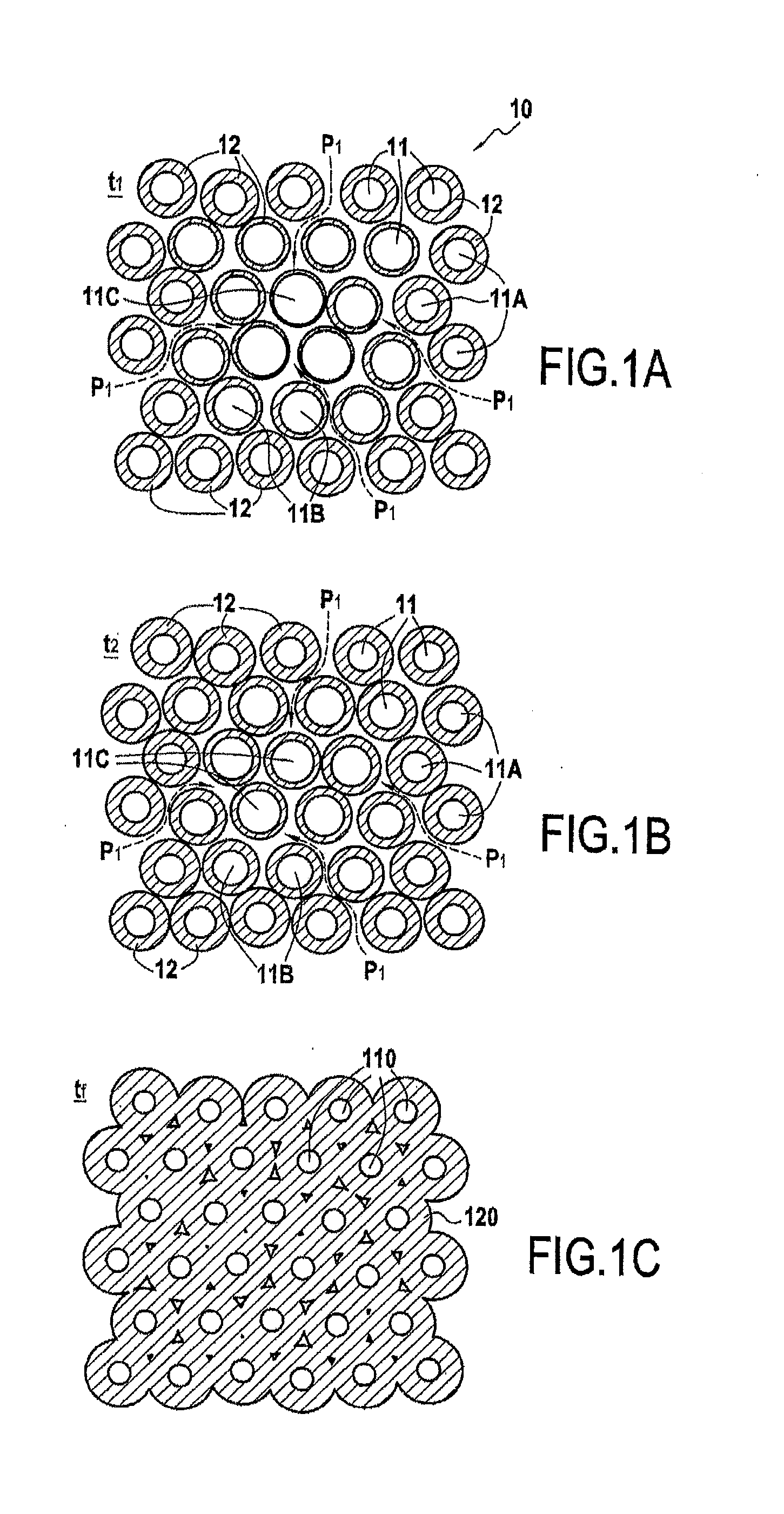
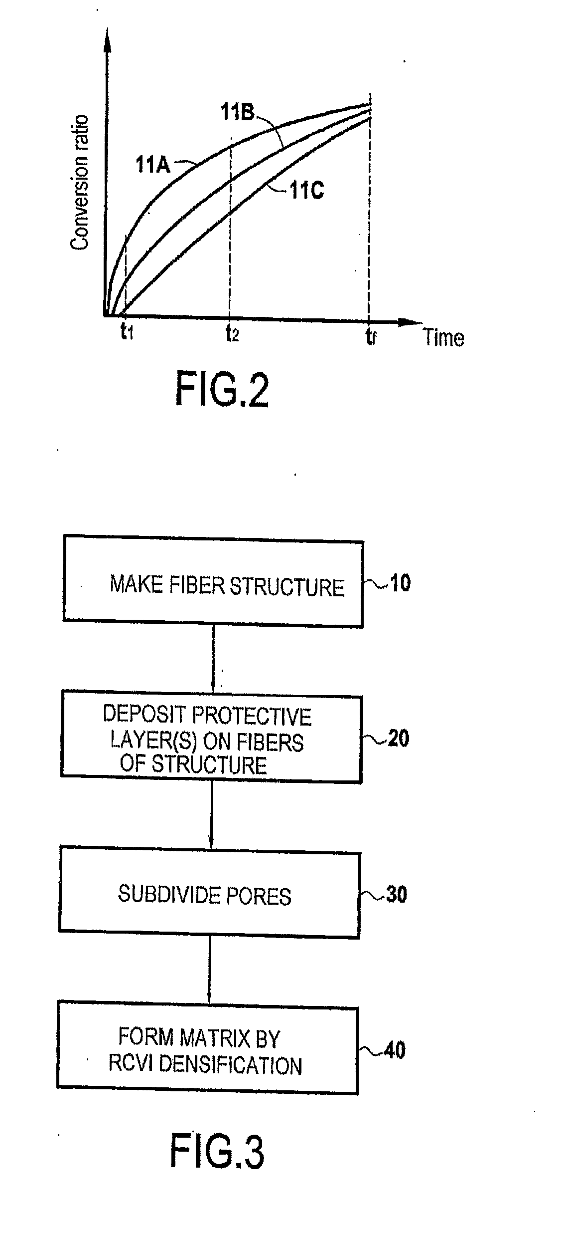
[0030]The present invention proposes a method of densifying a porous substrate with a carbide matrix obtained by reactive chemical vapor infiltration (RCVI) performed using a reactive gas composition having no carbon and suitable for reacting with carbon that is present in the substrate in order to form one or more carbides.

[0031]FIGS. 1A to 1C show how RCVI densification progresses in a porous substrate 10 constituted by a powder of carbon grains 11 of submicrometer size, i.e. of size less than one micrometer, or of micrometer size, i.e. of size greater than or equal to one micrometer. The powder is infiltrated with a reactive gas phase P1 suitable for forming at least one carbide by reaction between the carbon of the grains 11 and the gas phase P1. In the presently-described example, the reactive gas phase is constituted by TiCl4 that, on contact with grains of carbon, serves to form a titanium carbide (TiC) matrix. The carbide layer grows locally around each carbon-containing gra...


PUM

PropertyMeasurementUnit
Pressureaaaaaaaaaa
Structureaaaaaaaaaa

Abstract

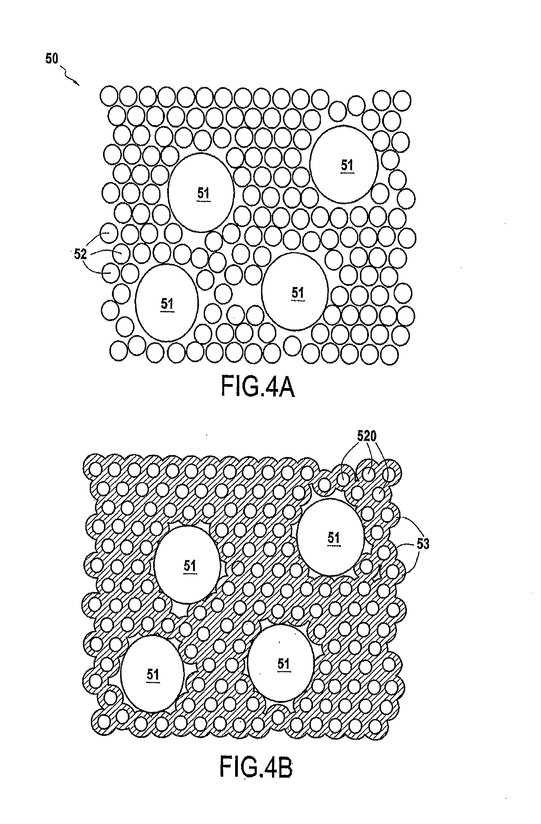
A method of densifying a porous substrate with a matrix, includes subdividing the pores present in the porous substrate so as to form in the substrate a network of micropores, the subdividing being performed with a filler composition comprising at least one carbon-containing phase or carbide-containing phase that is accessible via the network of micropores; and infiltrating the network of micropores formed by the filler material by reactive chemical vapor infiltration, the infiltration being performed with a reactive gas composition that does not contain carbon and that includes at least one element suitable for reacting with the carbon of the filler composition in order to form a carbide.

Description

BACKGROUND OF THE INVENTION[0001]The present invention relates to a method of densifying a porous substrate with a matrix presenting a continuous carbide phase. The invention applies particularly but not exclusively to making parts out of ceramic matrix composite (CMC) material formed by refractory fiber reinforcement (carbon or ceramic fibers) densified with a matrix that is ceramic, at least in part. Examples of CMCs are C / SiC composites (carbon fiber reinforcement and silicon carbide matrix), C / C—SiC composites (carbon fiber reinforcement and matrix comprising both a carbon phase, generally closer to the fibers, and a silicon carbide phase), and SiC / SiC composites (both reinforcing fibers and matrix made of silicon carbide).[0002]Numerous techniques exist for densifying porous substrates enabling an at least partially carbide matrix to be formed within the substrate. These techniques include in particular:[0003]a) Chemical vapor infiltration (CVI) which consists in infiltrating a...

Claims


Application Information

Patent Timeline
IPC IPC(8): C04B35/56C23C16/02C04B35/565C04B35/628C04B35/80C23C16/32C23C16/34C23C16/455
CPCC23C16/0272C04B35/565C04B35/5611C04B35/5607C04B35/806C23C16/34C23C16/0209C23C16/45557C23C16/325C23C16/32C04B35/62884C04B35/563C04B35/573C04B35/62868C04B35/62873C04B35/65C04B35/83C04B2235/3251C04B2235/422C04B2235/48C04B2235/5224C04B2235/5244C04B2235/5248C04B2235/5252C04B2235/5256C04B2235/5436C04B2235/5445C04B2235/614C04B2235/616C04B2235/80C04B35/5622C04B35/80
Inventor JACQUES, SYLVAINLEDAIN, OLIVIERMAILLE, LAURENCEDELCAMP, ADRIENPIQUERO, THIERRY
Owner SAFRAN CERAMICS SA
Why Eureka
Eureka Blog
Learn More