
Outer wall mounting member and outer wall structure

Active Publication Date: 2016-02-11
NICHIHA CORP
View PDF4 Cites 7 Cited by
  • Summary
  • Abstract
  • Description
  • Claims
  • Application Information

AI Technical Summary

Benefits of technology

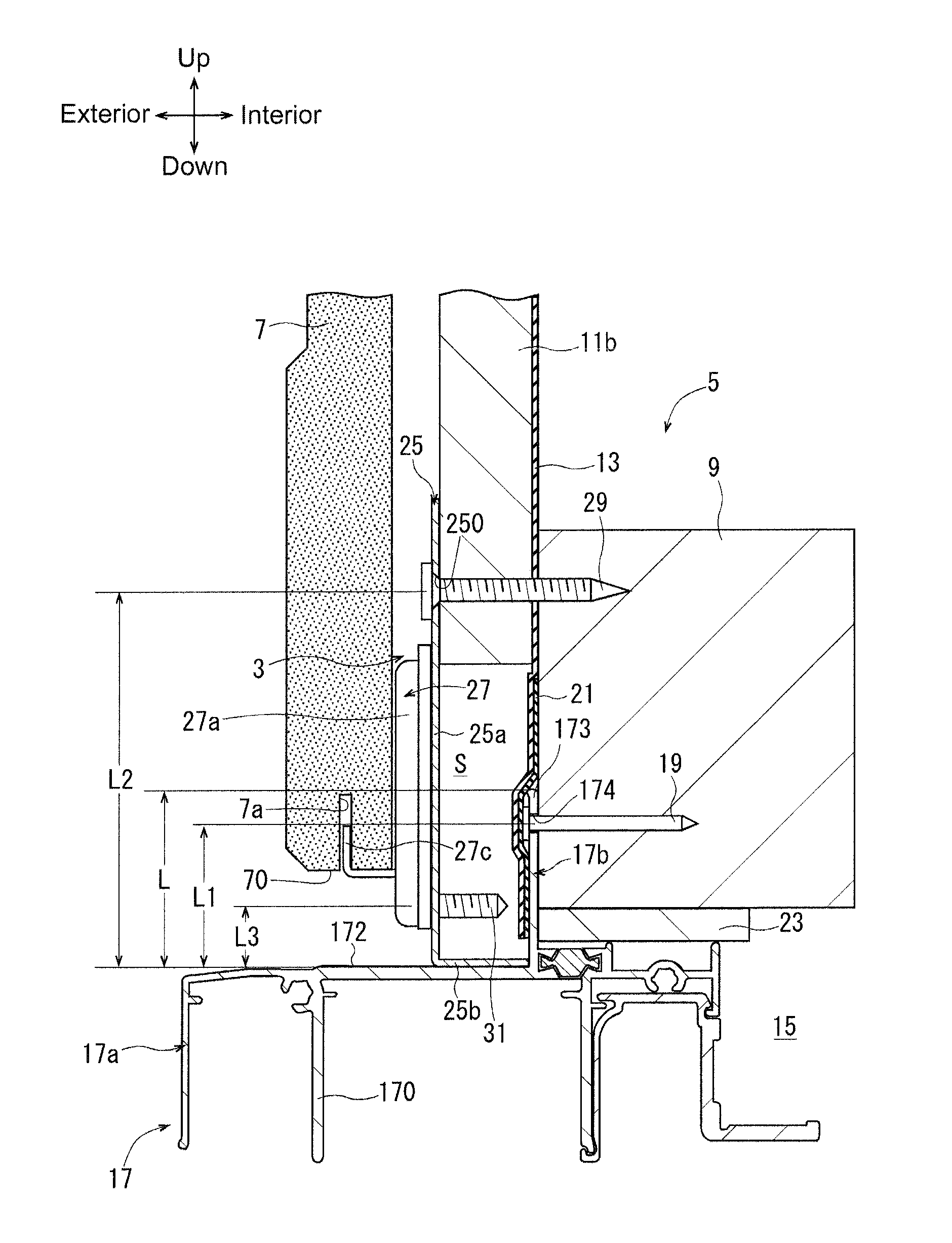
The goal is to create an outer wall mounting member and structure that can securely mount building materials onto the building body, while maintaining the waterproofness of the building and preventing any decrease in aesthetic appearance around the opening member.

Problems solved by technology

However, with this configuration, rainwater or the like may enter the interior side of the building body from the hole formed in the flange, thus causing a reduction in the waterproofness of the building.
On the other hand, when a short screw that does not reach the flange and the building body is used to fax the securing member to the furring strip member to maintain the waterproofness of the building, it is likely that the securing member may not be fully fixed to the building body, thus posing a concern that the exterior building material may become unstable after mounted onto the building body.
Moreover, if the securing member is fixed to a thick furring strip member having an enough length from the flange, the gap between the exterior building material and the opening member body is increased after the exterior building material is secured to the securing member, resulting in deterioration in the aesthetic appearance of the building.
Therefore, the nail head or screw head appears in the outer surface of the exterior building material to cause the deterioration in the aesthetic appearance around the opening member.

Method used


Image

  • Outer wall mounting member and outer wall structure
  • Outer wall mounting member and outer wall structure
  • Outer wall mounting member and outer wall structure

Examples


Embodiment Construction

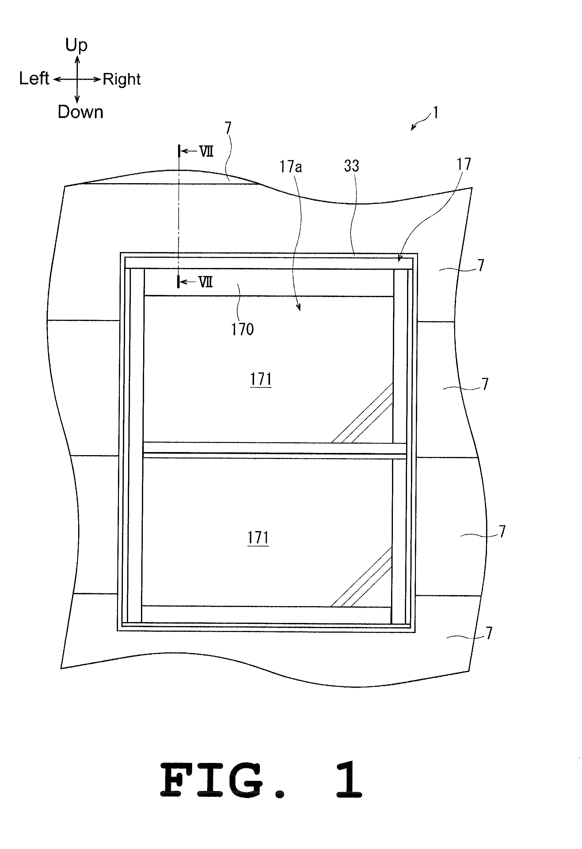
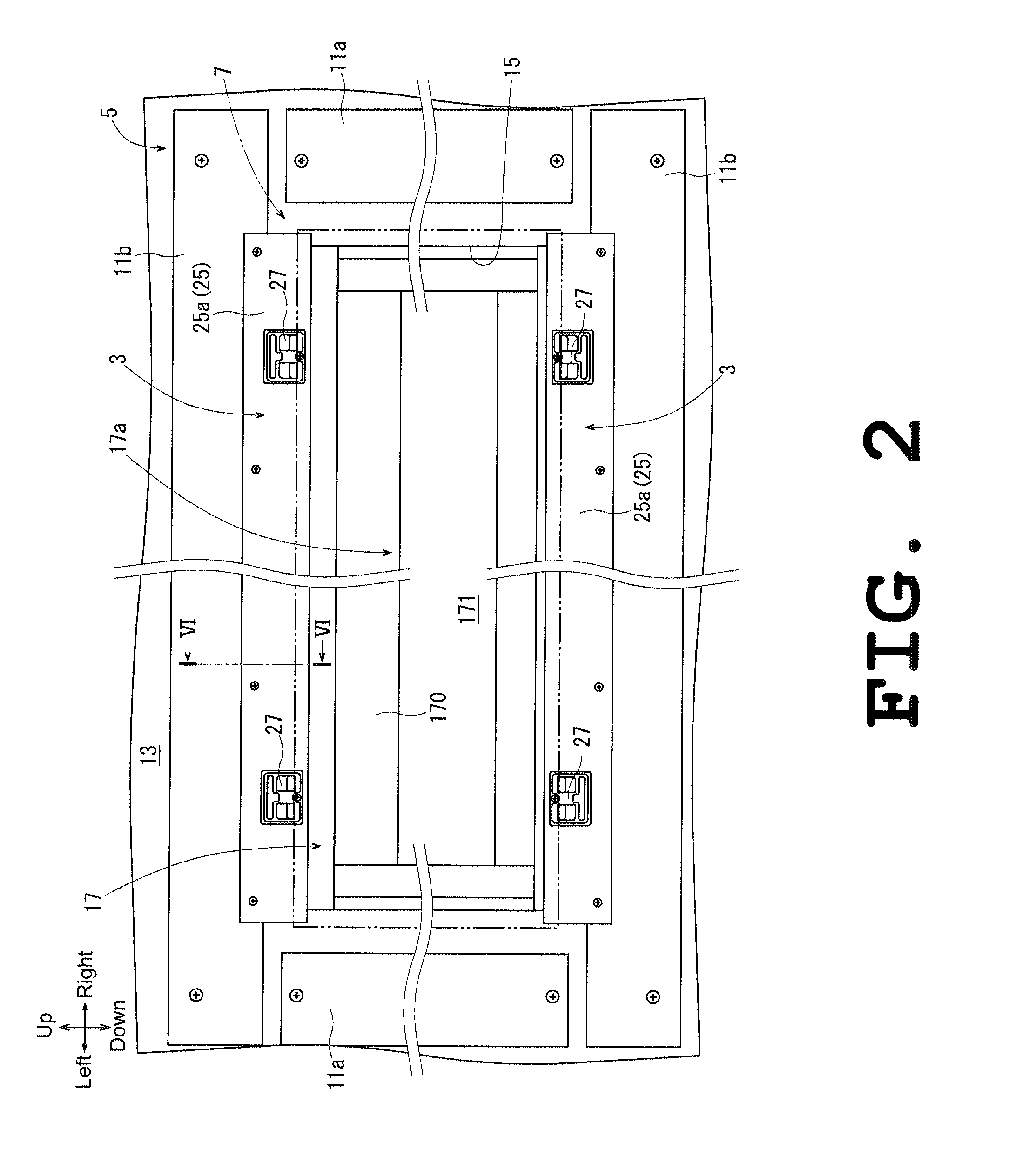
[0021]An outer wall mounting member is for mounting a ceramic exterior building material onto a building body in at least one of an upside and a downside of an opening member provided in an opening portion formed in the building body. The opening member includes: an opening member body that has a frame form; and a flange that extends outward at a substantially right angle from an outer surface of the opening member body to be fixed on an exterior side of the building body at a position with a first distance (i.e., a flange-fixing-position) away from the opening member body. An engaging groove is formed in an end face of the exterior building material. The outer wall mounting member includes a supporting plate and a securing member. The supporting plate having a plate form, is to be fixed to the building body in at least one of the upside portion and the downside portion of the opening member body by means of a nail or a screw (i.e., a supporting-plate-fitting) at a position with a s...


PUM


Abstract

An outer wall structure of the invention includes an outer wall mounting member composed of a supporting plate and a plurality of securing members. The supporting plate includes a plate body and a positioning portion. With this outer wall structure, the plate body is fixed to a horizontal furring strip member and a frame member in an upside portion and a downside portion of a sash body of a window sash at a second distance away from an outer surface of the sash body. The securing members are fixed to the plate body at a third distance away from the outer surface of the sash body. In this outer wall structure, the position at the second distance is farther away from the outer face than the position at a distance from the outer surface of the sash body to a distal end portion of a flange of the sash body.

Description

CROSS REFERENCE TO RELATED APPLICATIONS[0001]This application is based on Japanese Patent Application No. 2014-162988 filed with the Japanese Patent Office on Aug. 8, 2014, the entire content of which is hereby incorporated by reference.BACKGROUND OF THE INVENTION[0002]1. Field of the Invention[0003]The present invention relates to an outer wall mounting member and an outer wall structure.[0004]2. Description of the Related Art[0005]An outer wall structure for mounting an exterior building material (e.g., a ceramic exterior building material) to a building body formed by a plurality of column members, furring strip members and the like, is known to be used, for example, for wooden buildings such as houses. Conventionally, a configuration in which the exterior building material is directly fixed to the building body by nailing or screwing has been used to mount the exterior building material onto the building body. However, with the outer wall structure for which nailing or the like ...

Claims


Application Information

Patent Timeline
IPC IPC(8): E04F13/08E04B1/41
CPCE04F13/0826E04B2001/405E04B1/40E04F13/085E06B1/62E04F19/06E04B1/388E04B2001/389
Inventor SAWADA, KOJI
Owner NICHIHA CORP
Learn More