Molten air rechargeable batteries
a rechargeable battery and air technology, applied in the direction of molten electrolytes, cell components, electrochemical generators, etc., can solve the problems of low capacity and achieve the effect of prolonging the cycle life of the battery
- Summary
- Abstract
- Description
- Claims
- Application Information
AI Technical Summary
Benefits of technology
Problems solved by technology
Method used
Image

Examples
example 1
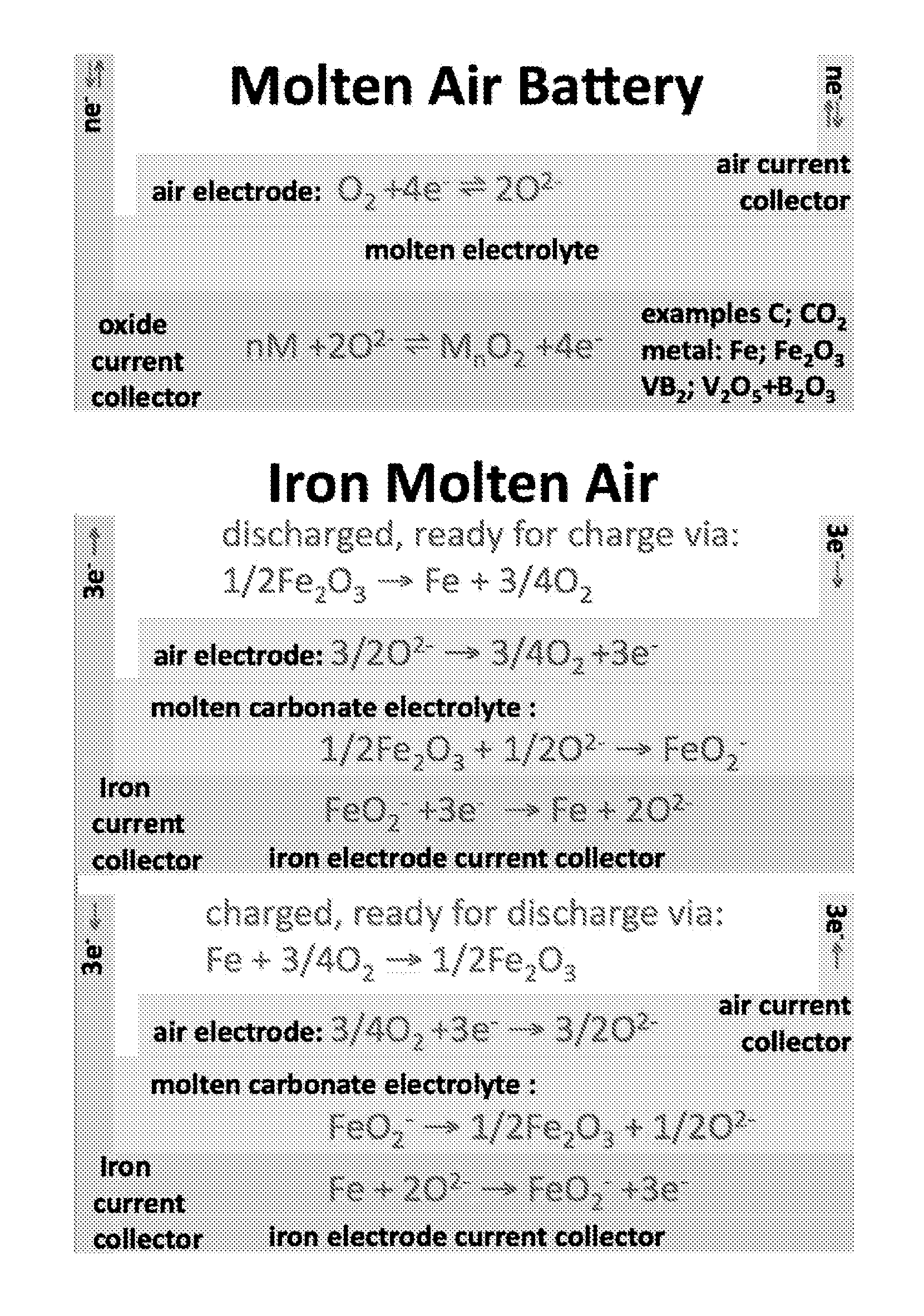
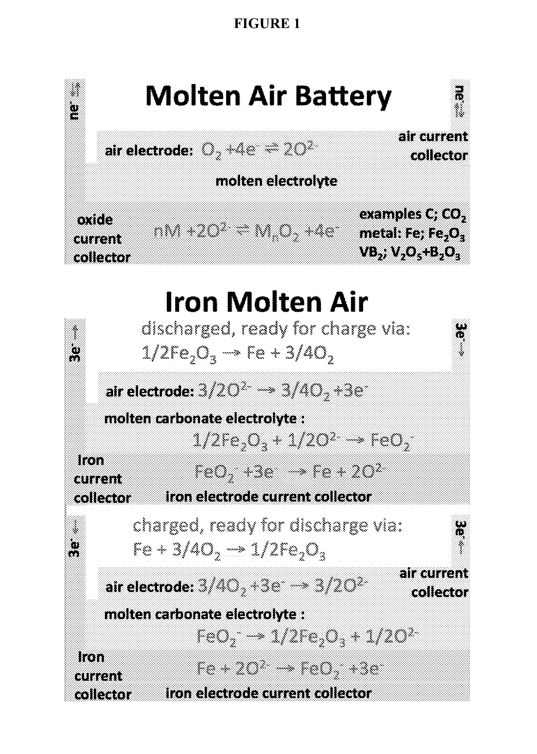
Iron Molten Air Rechargeable Battery
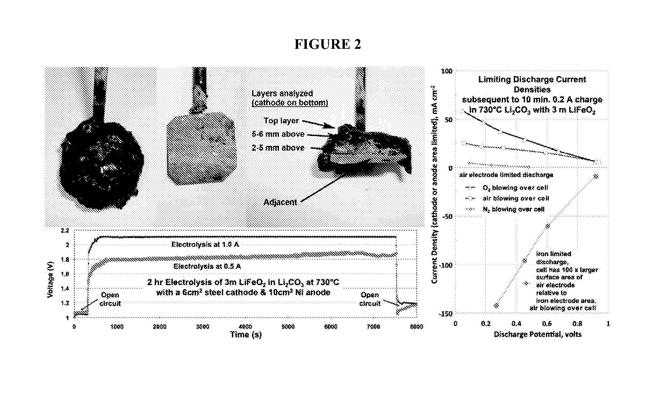
[0118]Iron metal synthesis in molten carbonates is conducted via constant current electrolyses. As shown in the the constant current electrolyses (left side) of FIG. 2, iron oxide (as hematite, Fe2O3, or magnetite, Fe3O4) readily electrolyzes to iron which forms on an iron or platinum cathode. See also, e.g., Licht et al., Adv. Mat., 47, 5592-5612, 2011. Post electrolysis, iron deposited on an extracted cathode is shown with an overlay of electrolyte in the top left of FIG. 2. The deposit is easily peeled from the cooled cathode, and after peeling, the post electrolysis steel foil cathode is shown (middle photo of FIG. 2) ready for a repeat electrolysis. A cross-section of the cathode deposit is shown in the right photo of FIG. 2, in which the iron deposit is evident. The right side of FIG. 2 shows discharge polarization (following electrochemical charge to form iron) of the air electrode (planar Ni, a planar disk of wound Ni wire, or planar Ir yi...
example 1a
Lower Temperature Iron Molten Air Rechargeable Battery
[0124]FIG. 8 shows the cycled charge / discharge behaviour of a eutectic Li0.87Na0.63K0.50CO3 molten electrolyte low temperature iron molten air battery at 500° C. (top row) or 600° C. (bottom 3 rows). The 500° C. battery was cycled at 0.04 A charge and discharged at 100Ω, while the 600° C. battery was cycled at 0.01 A charge and discharged at 200Ω. The eutectic molten electrolyte contained 3 m Li2O with 0.05 m Fe2O3.
[0125]The top row of FIG. 8 presents the low relative discharge to charge voltage over 7 cycles at 500° C. It can seen that 4 cycles are required to reach a level charging potential. The 500° C. 100Ω discharge exhibits a small shoulder which develops at 0.8 V. At 600° C., this shoulder discharge is sustained at ˜1 V, and increases further to ˜1.1 V over a 200Ω load. At heavier load, the polarization is larger. Over a 10Ω constant load the discharge voltage is 0.1 V, 0.2 V or 0.5 V at 395° C., 500° C. and 600° C., resp...
example 2
Carbon Molten Air Rechargeable Battery
[0127]Carbon formation during molten carbonate electrolysis provides charging of the carbon molten air batteries described herein. Molten carbonate cells have been widely probed as robust fuel cells, and this, in combination with the reverse of this process (electrolysis for carbon capture) provide new opportunities for high capacity carbon molten air reversible battery storage.
[0128]FIG. 9 depicts charging the carbon molten air battery. The left hand photo shows coiled 5 cm2 nickel (air) & 5 cm2 steel (cathode) electrodes prior to electrode insertion (as used in the top and middle traces in the charge reactions shown below in FIG. 9. The left hand photo shows the post-electrolysis reusable air electrode. The middle photo shows the thick carbon layer formed on the 5 cm2 steel cathode during a 4 hour 1 A charge in molten carbonate. The electrodes were photographed after extraction and without washing. The graph in FIG. 9 shows the electrolysis po...
PUM
 Abstract
Description
Claims
Application Information
 - R&D
- Intellectual Property
- Life Sciences
- Materials
- Tech Scout
- Unparalleled Data Quality
- Higher Quality Content
- 60% Fewer Hallucinations
Browse by: Latest US Patents, China's latest patents, Technical Efficacy Thesaurus, Application Domain, Technology Topic, Popular Technical Reports.
© 2025 PatSnap. All rights reserved.Legal|Privacy policy|Modern Slavery Act Transparency Statement|Sitemap|About US| Contact US: help@patsnap.com