Device and method for the autonomous bootstrapping of unified sentience

a technology of unified sentience and bootstrapping, applied in the field of artificial intelligence and machine consciousness, can solve the problems of inability to isolate the formation of associative chains, the burden on memory and processors, and the inability to identify valuable activation patterns within the cortical algorithm,

Active Publication Date: 2015-12-31
THALER STEPHEN L
View PDF13 Cites 12 Cited by
  • Summary
  • Abstract
  • Description
  • Claims
  • Application Information

AI Technical Summary

Benefits of technology

[0021]The system operates similarly to the interaction between the cortex and thalamus in the human brain, with the monitoring sensor and thalamobot, tantamount to the reptilian brain, shifting its attention to newly emerging neural activation patterns appearing within the visual display. If multiple visual outputs are used, the system can serve in the detection of important spatial-temporal connections / correlations between emergent patterns in the various displays thus unifying them into more complex associations, achieving complex graph analysis without a super-computer.

Problems solved by technology

When attempts are made to build artificial neural systems approaching the size and complexity of the human cortex, memory and processors are so heavily taxed that any monitoring algorithm needs to run either intermittently as a separate thread or process on the same computational platform.
Furthermore, as these synthetic cortical systems become more extensive and complex it becomes increasingly difficult to isolate the formation of associative chains that reveal important relationships or the emergence of novel patterns tantamount to ideas and improvisational strategies.
In the first case of intermittent execution of the monitoring algorithm, valuable activation patterns may be missed within the cortical algorithm.
In the second case of threads executing the thalamic algorithm in parallel with the cortical, the states of the synthetic cortex must be passed via immense data structures, resulting in significant delays in the evaluation of cortical activation patterns.
However, such systems were restricted in part by typical processing bottlenecks.

Method used


Image

  • Device and method for the autonomous bootstrapping of unified sentience
  • Device and method for the autonomous bootstrapping of unified sentience
  • Device and method for the autonomous bootstrapping of unified sentience

Examples


Embodiment Construction

[0043]In the following detailed description numerous specific details are set forth in order to provide a thorough understanding of the invention. However, it will be understood by those skilled in the art that the present invention may be practiced without these specific details. For example, the invention is not limited in scope to the particular type of industry application depicted in the figures. In other instances, well-known methods, procedures, and components have not been described in detail so as not to obscure the present invention.

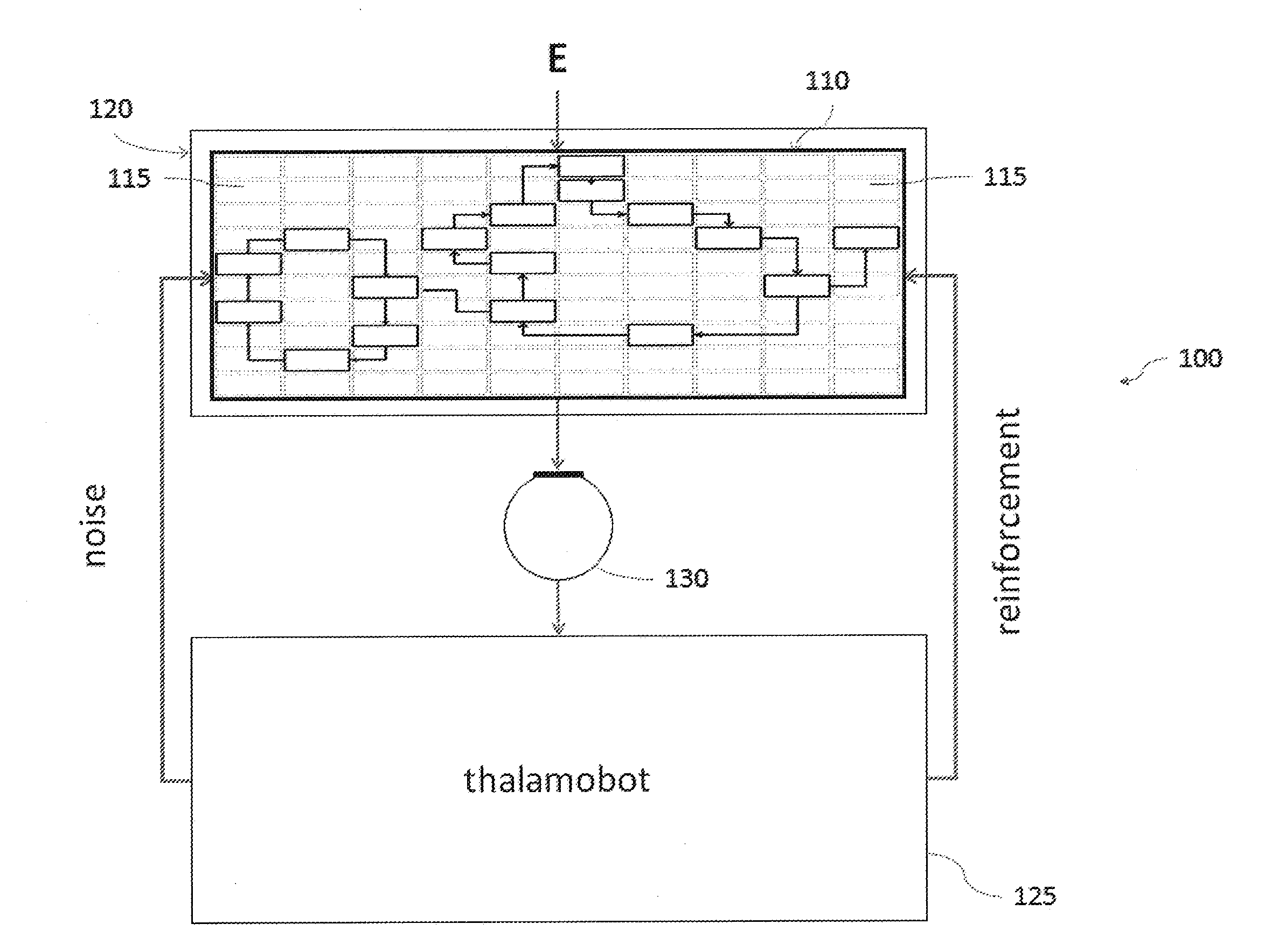
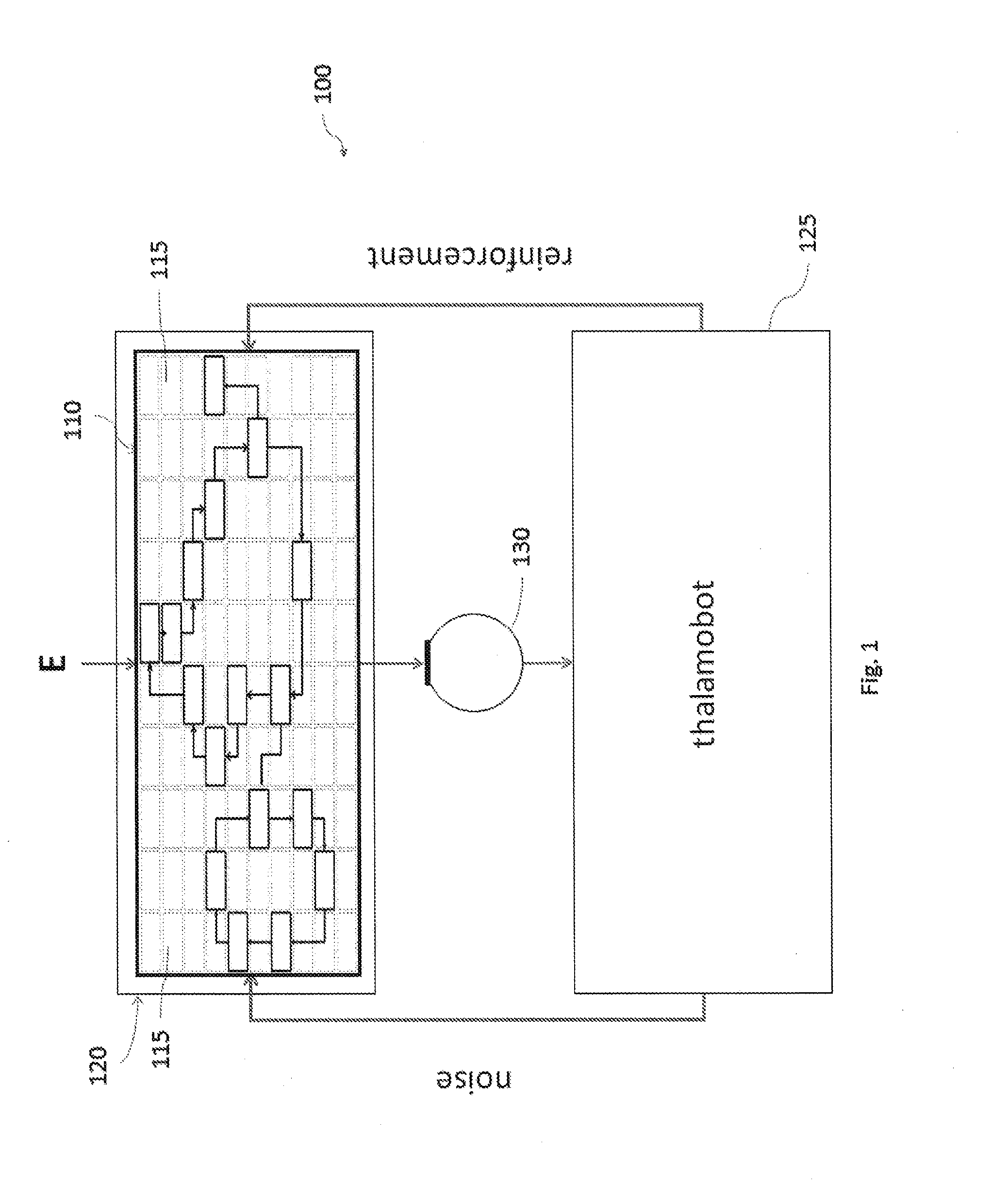
[0044]The following terms are defined to provide a framework for the discussion of embodiments of the invention:[0045]Neural Module (115): an individual neural network in the form of an input-output mapping. Herein, adaptive multilayer neural modules have been used for proof-of-principle experiments.[0046]Synapse / Synaptic[0047]Connection Weight: Numerically-based connections between neurons within a neural module or between neural modules thems...


PUM


Abstract

A system for monitoring an environment may include an input device for monitoring and capturing pattern-based states of a model of the environment. The system may also include a 5 thalamobot embodied in at least a first processor, in which the first processor is in communication with the input device. The thalamobot may include at least one filter for monitoring captured data from the input device and for identifying at least one state change within the captured data. The system may also include at least one critic and/or at least one recognition system.

Description

CROSS-REFERENCE TO RELATED APPLICATIONS[0001]This application claims priority to U.S. Provisional Patent Application Ser. No. 61 / 924,624, and incorporates the entirety of the disclosure therein by reference.TECHNICAL FIELD OF THE INVENTION[0002]The invention relates generally to the fields of both artificial intelligence and machine consciousness and, more particularly, to a method and device for the unification and origination of knowledge within connectionist systems.BACKGROUND OF THE INVENTION[0003]The thalamus has been described as the “eyeball” or “projection screen” of the brain, monitoring the continuously evolving cortical activity that may be thought of as the brain's “multimedia show,” while also serving as a trigger for global or “volume” release of neurotransmitters into the cortex. When attempts are made to build artificial neural systems approaching the size and complexity of the human cortex, memory and processors are so heavily taxed that any monitoring algorithm nee...

Claims


Application Information

Patent Timeline
Patent Type & Authority Applications(United States)
IPC IPC(8): G06N3/063G06N3/08
CPCG06N3/063G06N3/0454Y04S10/54G06N3/08G06N3/045
Inventor THALER, STEPHEN L.
Owner THALER STEPHEN L
Why Eureka
Try Eureka