
Piezoelectric material, piezoelectric element, and electronic equipment

Active Publication Date: 2015-12-24
CANON KK
View PDF5 Cites 18 Cited by
  • Summary
  • Abstract
  • Description
  • Claims
  • Application Information

AI Technical Summary

Benefits of technology

The present invention provides a lead- and potassium-free piezoelectric material that has a high piezoelectric constant and good insulation properties. It also provides a piezoelectric element, a multilayered piezoelectric element, liquid discharge head, liquid discharge apparatus, ultrasonic motor, optical apparatus, vibratory apparatus, dust removing device, image pickup apparatus, and electronic equipment that includes the piezoelectric material. The piezoelectric material described in the present invention is lead-free, has a low environmental load, and is potassium-free, which improves its sinterability and moisture resistance.

Problems solved by technology

However, PZT contains lead as an A site element, and its effect on the environment is regarded as a problem.
Potassium is responsible for poor sinterability and low moisture resistance.

Method used


Image

  • Piezoelectric material, piezoelectric element, and electronic equipment
  • Piezoelectric material, piezoelectric element, and electronic equipment
  • Piezoelectric material, piezoelectric element, and electronic equipment

Examples


examples

[0137]Although a piezoelectric material according to an embodiment of the present invention is further described in the following examples, the present invention is not limited to these examples.

example 43

[0164]The raw materials corresponding to Example 1 were weighed as described below.

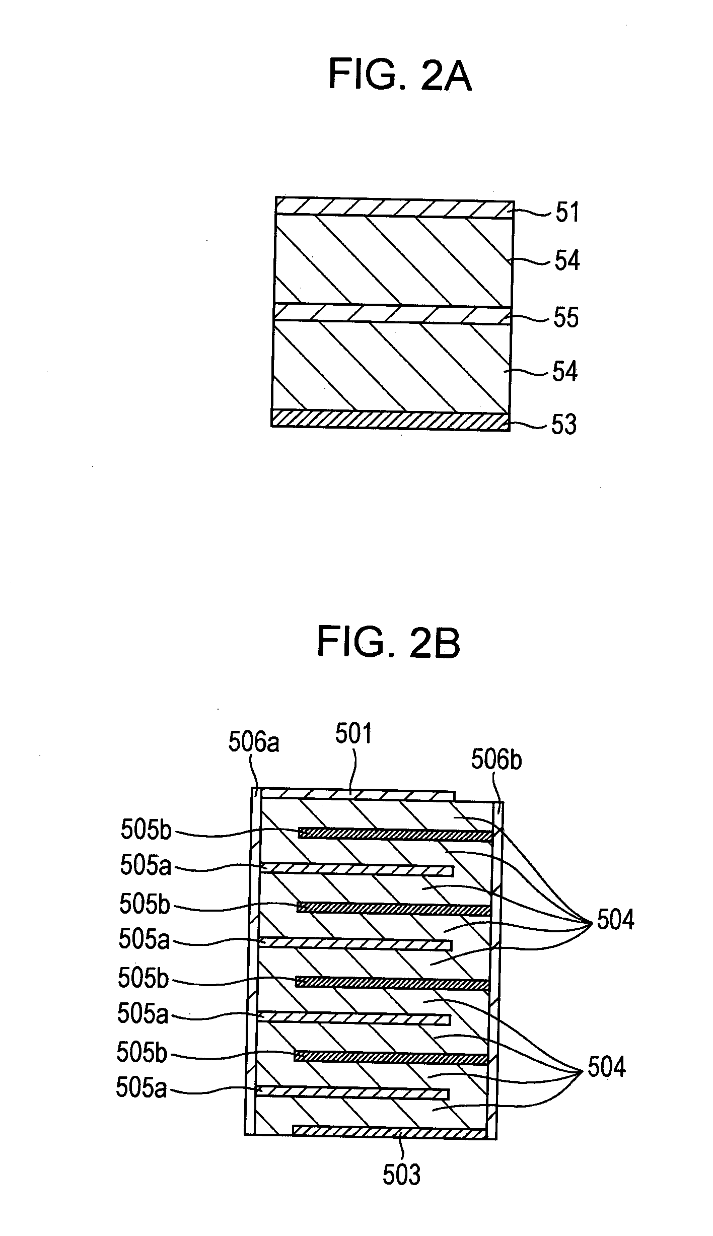
[0165]Powders of sodium carbonate (Na2CO3), niobium oxide (Nb2O5), barium titanate (BaTiO3), lanthanum oxide (La2O3), and copper oxide (CuO) were weighed such that Na, Nb, Ba, Ti, La, and Cu satisfied the composition of Example 1 described in Table 1. The weighed raw powders were mixed in a ball mill overnight and was calcined at a temperature in the range of 1000° C. to 1100° C. to yield a calcined powder. The calcined powder was mixed with a solvent, a binder (PVB), and a plasticizer (dibutyl phthalate) to prepare a slurry. The slurry was formed into a green sheet having a thickness of 50 μm using a doctor blade method.

[0166]An electrically conductive paste for an internal electrode was applied to the green sheet. The electrically conductive paste was a 70% Ag-30% Pd alloy (Ag / Pd=2.33) paste. Nine of the green sheets to which the electrically conductive paste had been applied were stacked and were f...

example 44

[0170]Powders of sodium niobate (NaNbO3), barium titanate (BaTiO3), lanthanum oxide (La2O3), and copper oxide (CuO) were weighed such that Na, Nb, Ba, Ti, La, and Cu satisfied the composition of Example 2 described in Table 1. The weighed raw powders were mixed in a ball mill overnight and was calcined at a temperature in the range of 1000° C. to 1100° C. to yield a calcined powder.

[0171]The calcined powder was mixed with a solvent, a binder (PVB), and a plasticizer (dibutyl phthalate) to prepare a slurry. The slurry was formed into a green sheet having a thickness of 50 μm using a doctor blade method. An electrically conductive paste for an internal electrode was applied to the green sheet. The electrically conductive paste was a Ni paste. Nine of the green sheets to which the electrically conductive paste had been applied were stacked and were heat-pressed.

[0172]The heat-pressed layered body was fired in a tubular furnace. The heat-pressed layered body was fired to a temperature u...


PUM

PropertyMeasurementUnit
Weightaaaaaaaaaa
Weight ratioaaaaaaaaaa
Piezoelectricityaaaaaaaaaa

Abstract

There is provided a lead- and potassium-free piezoelectric material having a high piezoelectric constant and a satisfactory insulation property and a piezoelectric element that includes the piezoelectric material. The piezoelectric material contains a perovskite-type metal oxide having the general formula (1): (NaxBa1-y)(NbyTi1-y)O3 (wherein x satisfies 0.80≦x≦0.95, and y satisfies 0.85≦y≦0.95); and at least one rare-earth element selected from La, Pr, Nd, Pm, Sm, Eu, Gd, Tb, Dy, Ho, Er, Tm, Yb, and Lu, wherein the rare-earth element content is more than 0 mol % and 5 mol % or less of the amount of perovskite-type metal oxide. The piezoelectric element includes the piezoelectric material.

Description

TECHNICAL FIELD[0001]The present invention relates to a piezoelectric material and more particularly to a lead-free piezoelectric material. The present invention also relates to a piezoelectric element, a multilayered piezoelectric element, a liquid discharge head, a liquid discharge apparatus, an ultrasonic motor, an optical apparatus, a vibratory apparatus, a dust removing device, an image pickup apparatus, and electronic equipment, each including the piezoelectric material.BACKGROUND ART[0002]In general, piezoelectric ceramics are ABO3 perovskite-type metal oxides, such as lead zirconate titanate (hereinafter referred to as “PZT”). However, PZT contains lead as an A site element, and its effect on the environment is regarded as a problem. Thus, there is a demand for piezoelectric ceramics of lead-free perovskite-type metal oxides.[0003]NPL 1 discloses that, in a solid solution of a small amount of barium titanate in an antiferroelectric material sodium niobate, sodium niobate con...

Claims


Application Information

Patent Timeline
IPC IPC(8): C04B35/495H01L41/083H01L41/047H04N5/217H02N2/00B06B1/06G02B7/09G02B27/00H01L41/18B41J2/14
CPCC04B35/495C04B2235/768H01L41/083H01L41/0471B41J2/14201H02N2/001B06B1/06G02B7/09G02B27/0006H04N5/2171C04B2235/3201C04B2235/3215C04B2235/3227C04B2235/3255C04B2235/3236C04B2235/3281H01L41/18B41J2/14233H02N2/106H02N2/163B41J2202/03C04B2235/3224C04B2235/3232C04B2235/6567C04B2235/786H10N30/50H10N30/2047H10N30/8542H10N30/097H04N23/811H10N30/85H10N30/871
Inventor HAYASHI, JUMPEIWATANABE, TAKAYUKIMURAKAMI, SHUNSUKEUEDA, MIKI
Owner CANON KK
Learn More