
Battery charging system using charger and driving control method of the charger thereof

a charging system and charger technology, applied in the direction of battery/fuel cell control arrangement, electric devices, transportation and packaging, etc., can solve the problem that the controller b>3/b> may not be able to adjust the output voltage vdc, the minimum driving time for detecting and dealing with the driving state of the charger may not be possible, etc. problem, to achieve the effect of increasing the driving time of the obc, preventing an increase in efficiency, and being more stab

Active Publication Date: 2015-12-03
HYUNDAI MOTOR CO LTD
View PDF2 Cites 10 Cited by
  • Summary
  • Abstract
  • Description
  • Claims
  • Application Information

AI Technical Summary

Benefits of technology

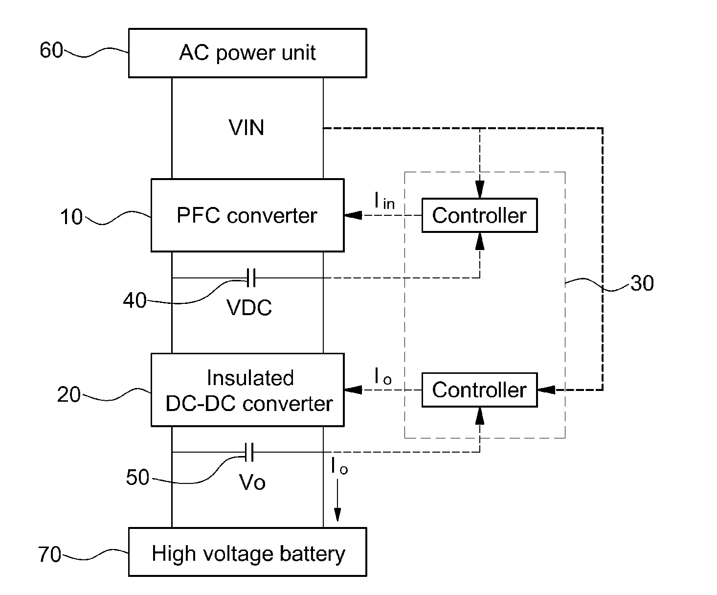
The present invention provides a battery charging system that uses a charger and a driving control method of the charger. The invention increases the driving time of the charger when there is an instantaneous power failure in the battery charging system, which allows for more precise information to be obtained and processed. This results in a reduction in the capacity of the capacitor, which decreases the cost of the battery charging system. Additionally, the invention prevents the charger from repeating the initial sequence due to the increased driving time and ensures a minimum driving time for a stable operation of the charger in an instantaneous power failure.

Problems solved by technology

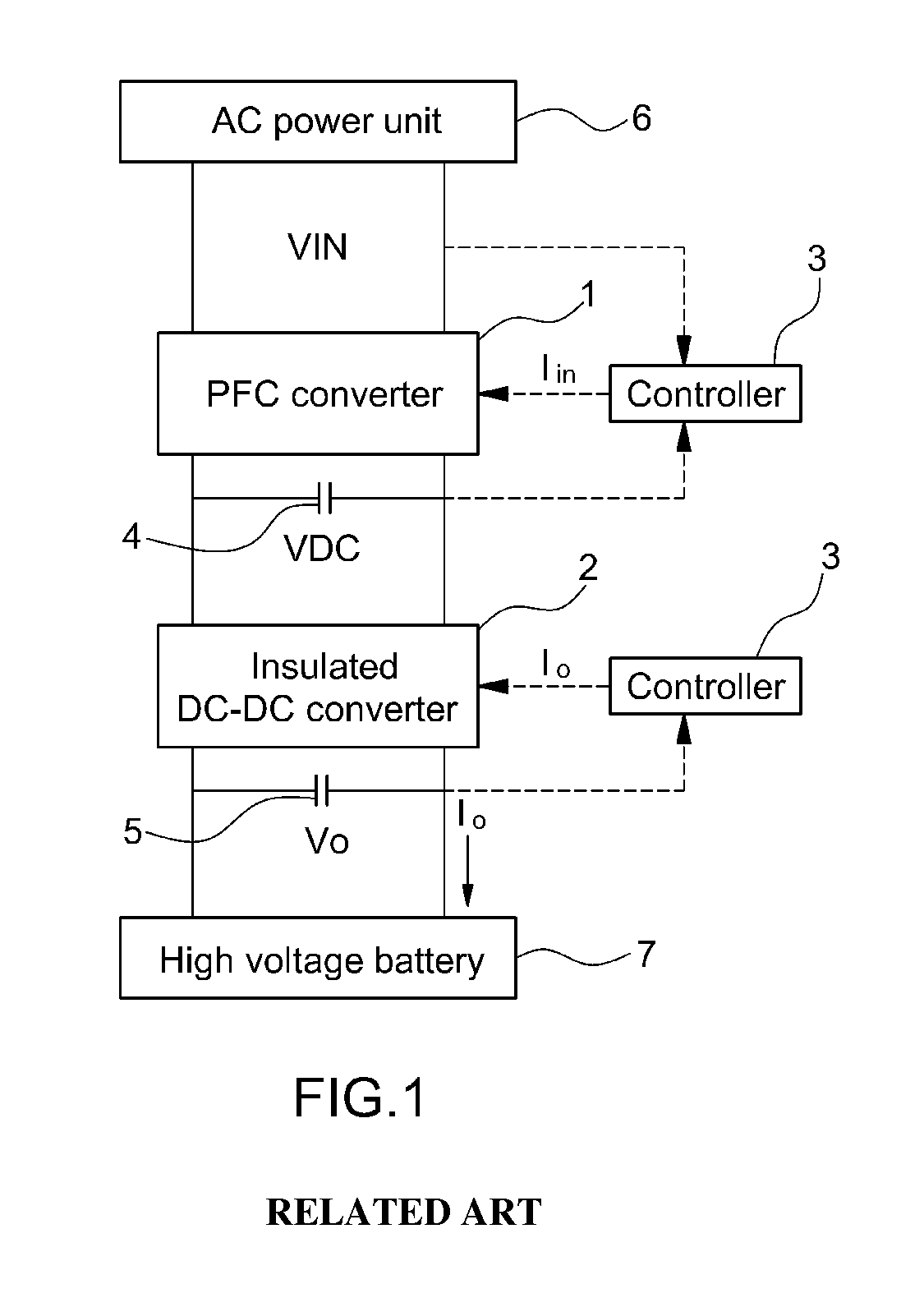
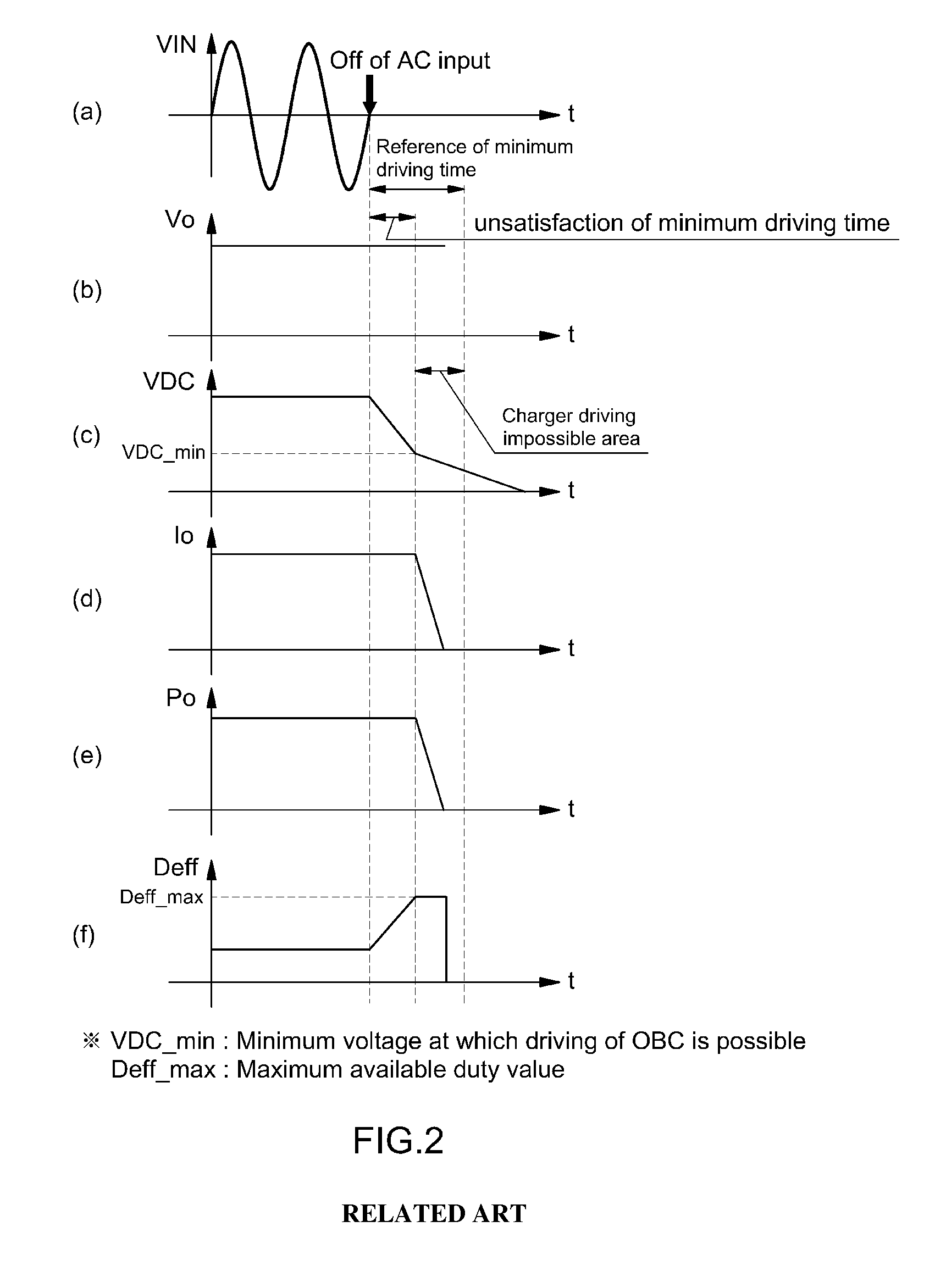
Hence, the PFC converter 1 is in an uncontrollable state due to loss of input, and the controller 3 may not be able to adjust the output voltage VDC of the PFC converter 1.
Therefore, a minimum driving time for detecting and dealing with the driving state of the charger may not be possible.
As a result, a malfunction of the OBC may be caused, and therefore, the vehicle may be in a dangerous situation.
However, this causes an increase in cost.
Third, the minimum driving time for a stable operation of the OBC in the instantaneous power failure may be secured, and thus it may be unnecessary to increase the capacity of the first capacitor connected to the output terminal of the PFC converter to form a high output voltage VDC of the PFC converter.

Method used


Image

  • Battery charging system using charger and driving control method of the charger thereof
  • Battery charging system using charger and driving control method of the charger thereof
  • Battery charging system using charger and driving control method of the charger thereof

Examples


Embodiment Construction

[0031]It is understood that the term “vehicle” or “vehicular” or other similar term as used herein is inclusive of motor vehicles in general such as passenger automobiles including sports utility vehicles (SUV), buses, trucks, various commercial vehicles, watercraft including a variety of boats and ships, aircraft, and the like, and includes hybrid vehicles, electric vehicles, plug-in hybrid electric vehicles, hydrogen-powered vehicles and other alternative fuel vehicles (e.g. fuels derived from resources other than petroleum). As referred to herein, a hybrid vehicle is a vehicle that has two or more sources of power, for example both gasoline-powered and electric-powered vehicles.

[0032]Although exemplary embodiment is described as using a plurality of units to perform the exemplary process, it is understood that the exemplary processes may also be performed by one or plurality of modules. Additionally, it is understood that the term controller / control unit refers to a hardware devi...


PUM


Abstract

A battery charging system using a charger and a driving control method of the charger thereof are provided which increase a driving time of the charger when an instantaneous power failure of charger input voltage occurs in the battery charging system. Thus, a sufficient time is secured for obtaining and processing more precise information regarding a driving state of the charger and the capacity of a capacitor is decreased compared to the related art.

Description

CROSS-REFERENCE TO RELATED APPLICATION[0001]This application claims under 35 U.S.C. §119(a) the benefit of Korean Patent Application No. 10-2014-0065034 filed May 29, 2014, the entire contents of which are incorporated herein by reference.BACKGROUND[0002](a) Technical Field[0003]The present invention relates to a battery charging system using a charger and a driving control method of the charger thereof, which increases the driving time of the charger during a power failure of the charger mounted within a vehicle.[0004](b) Background Art[0005]As air pollution caused by exhaust gas of vehicles increases due to the development of automobile industries, interest in reduction of the exhaust gas has increased. Thus, studies on environmentally-friendly vehicles capable of reducing exhaust gas have been actively conducted. The environmentally-friendly vehicles include a hybrid vehicle, a plug-in hybrid vehicle, an electric vehicle, a fuel cell vehicle, and the like. Among these vehicles, t...

Claims


Application Information

Patent Timeline
Patent Type & Authority Applications(United States)
IPC IPC(8): H02J7/00H02M1/42H02J7/02
CPCH02J7/0052H02M1/42H02J7/02H02M1/36H02M1/4208H02M3/33523H02J7/04B60L3/00B60L2240/547B60L2240/80B60L58/10H02J7/007Y02T10/70H02M1/0096H02M1/007H02J5/00H02J7/00
Inventor SEONG, HYUN WOOKKWAK, MU SHINCHUN, SHIN HYEJANG, HUI SUNG
Owner HYUNDAI MOTOR CO LTD
Learn More