
Solar spectrum selective absorption coating and its manufacturing method

a selective absorption and solar energy technology, applied in the direction of solar heat devices, ion implantation coatings, coatings, etc., can solve the problems of increasing the material cost, and the photothermal conversion efficiency of the heat collector is relatively low at working temperatures above 200° c, and achieves excellent spectral selectivity, low optical concentration, and reduced thickness of the ge layer

Inactive Publication Date: 2015-11-05
TAHOE TECH
View PDF1 Cites 8 Cited by
  • Summary
  • Abstract
  • Description
  • Claims
  • Application Information

AI Technical Summary

Benefits of technology

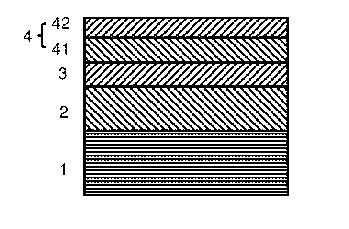
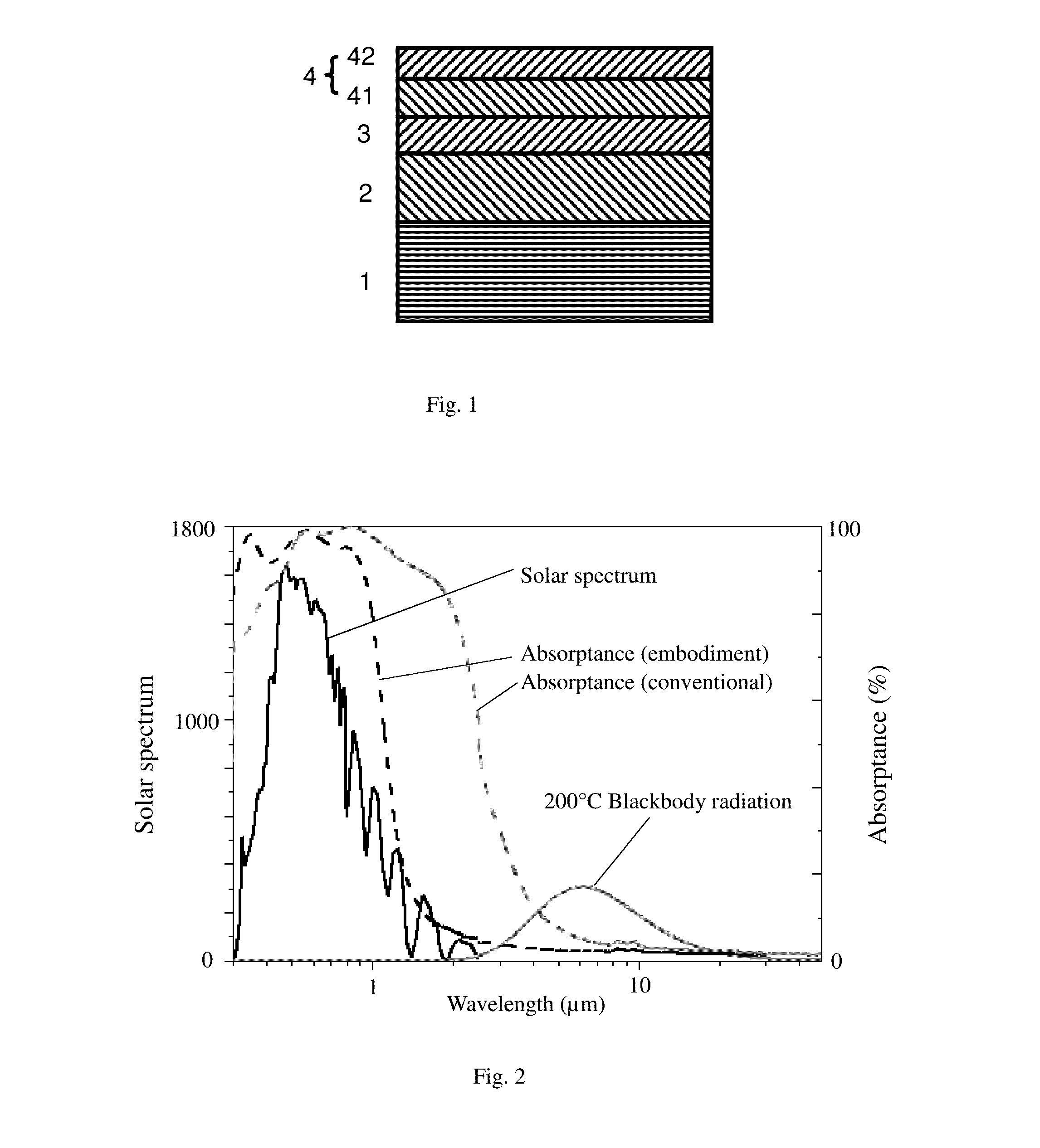
The present invention provides a solar spectrum selective absorption coating that has a unique structure and excellent spectral selectivity. It achieves effective absorption of solar energy and has low emissivity, making it suitable for low-concentration solar heat collectors. The coating consists of a three-layer structure: infrared reflective layer, absorption layer (Ge), and antireflection layer. The Ge layer acts as the absorption layer, achieving multiple reflections and absorptions of solar light. The antireflection layer uses stoichiometric dielectrics, which makes it suitable for large-scale, low-cost production. The coating has excellent thermal stability and can be easily fabricated. Overall, the present invention provides a highly efficient and cost-effective solar heat collector coating.

Problems solved by technology

Therefore, when these two categories of coating are used in heat collectors with low optical concentration, the photothermal conversion efficiency of the heat collector is relatively low at working temperatures above 200° C.
Moreover, the Ge film used in this device is relatively thick, increasing the material cost.
Thus, this design has the disadvantages that it is not suitable for large scale production and has poor thermal stability.

Method used


Image

  • Solar spectrum selective absorption coating and its manufacturing method
  • Solar spectrum selective absorption coating and its manufacturing method
  • Solar spectrum selective absorption coating and its manufacturing method

Examples


examples

[0041]Table 1 lists the thickness of various single layers of a selective absorption coating based on semiconductor germanium intrinsic absorption formed by magnetron sputtering in one embodiment.

TABLE 1Al layer / Ge layer / TiO2 layer / SiO2 layer / SamplenmnmnmnmEmbodiment150253171

[0042]The specific steps of the preparation process are as follows:

[0043]1) Cleaning of the glass plate: First, use a neutral wash solution to preliminarily clean the glass plate. Place the glass plate in the entrance chamber of the deposition equipment and perform second step cleaning using an RF plasma source to bombard the glass plate surface. The process parameters are as follows: RF source sputtering power is 200 w, working gas Ar (purity 99.99%) flow rate is 45 sccm, the working pressure is 9.8×10⁻² mTorr, and sputtering time is 360 s.

[0044]2) Pass the glass place from the entrance chamber to the sputtering chamber of the deposition equipment. The base pressure of the sputtering chamber is lower than 6×10−...


PUM

PropertyMeasurementUnit
refractive indexaaaaaaaaaa
thicknessaaaaaaaaaa
thicknessaaaaaaaaaa

Abstract

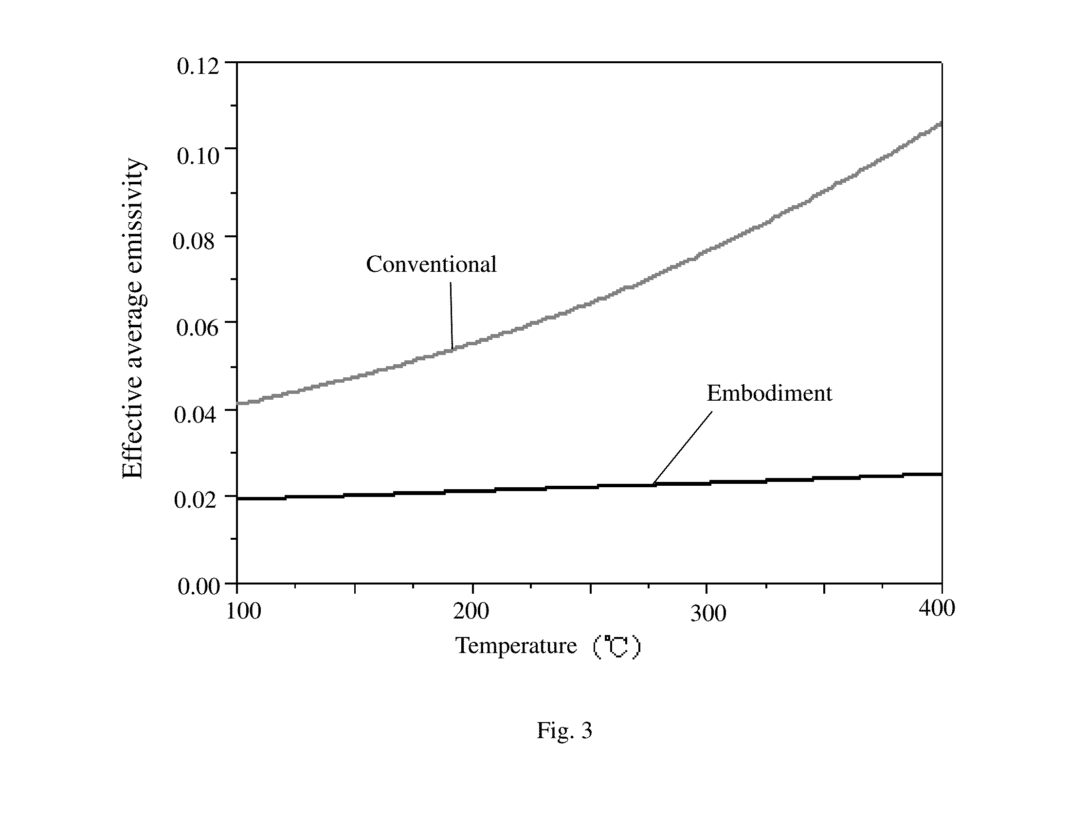
A solar spectrum selective absorption coating is disclosed. The coating includes, from the substrate to the air interface: substrate 1, infrared reflective layer 2, semiconductor absorption layer 3 (Ge), and antireflection layer 4 formed by a higher refractive-index dielectric layer 41 and a lower refractive-index dielectric layer 42. The solar spectrum selective absorption coating has superior spectrum selectivity, with a steep transition zone between solar absorption and infrared reflection zones. It has a relatively high absorptance α in the solar spectrum range (0.3-2 μm), and a very low absorptance / emissivity ε in the infrared thermal radiation spectrum range (2-50 μm); its a / c ratio is significantly higher than current commercially available products, making it suitable for medium-temperature solar heat collectors using low-power optical concentration. The manufacturing process is simple and does not require complex deposition equipment, so it is suitable for low-cost large-scale production.

Description

BACKGROUND OF THE INVENTION[0001]1. Field of the Invention[0002]This invention relates to a solar spectrum selective absorption coating and its manufacturing method, and in particular, it relates to such a coating based on an antireflection layer—semiconductormetal interference film system and its manufacturing method.[0003]2. Description of the Related Art[0004]Solar spectrum selective absorption coating is a key material in solar thermal energy conversion. On the one hand, it has relatively high absorptance in the solar energy spectrum range (0.3 μm-2.5 μm); on the other hand, it has relatively low absorptance, which is equal to emissivity numerically according to Kirchoff's law, in the infrared thermal radiation spectrum range (2.5 μm-50 μm), which suppresses heat dissipation due to infrared radiation. An important performance criterion that measures the selective absorption property of a material is the ratio of its absorptance for the solar energy spectrum a to its infrared em...

Claims


Application Information

Patent Timeline
Patent Type & Authority Applications(United States)
IPC IPC(8): F24J2/46F24J2/48C23C14/00C23C14/35C23C14/02
CPCF24J2/4652C23C14/35F24J2/485C23C14/0036C23C14/022C23C14/08C23C14/021C23C14/165C23C14/185Y02E10/40F24S70/30F24S70/225
Inventor XIANG, XIAODONGLIU, JINGWANG, HONG
Owner TAHOE TECH
Learn More