Eureka AIR delivers breakthrough ideas for toughest innovation challenges, trusted by R&D personnel around the world.

Metal Foam for Electrode of Secondary Lithium Battery, Preparing Method Thereof, and Secondary Lithium Battery Including the Metal Foam

a lithium battery and metal foam technology, applied in the direction of electrochemical devices, electrical equipment, metallic material coating processes, etc., can solve the problems of powder materials degrading and falling off, unavoidable new electrode material innovation concept, and increasing contact resistance, so as to improve charge and discharge efficiency, reduce contact resistance, and improve the effect of cycling characteristics

Active Publication Date: 2015-03-12
CELLMO MATERIALS INNOVATION INC
View PDF11 Cites 31 Cited by
  • Summary
  • Abstract
  • Description
  • Claims
  • Application Information

AI Technical Summary

Benefits of technology

The present invention provides a solution to improve the performance of metal foam structures used as electrodes in lithium batteries. The invention is about creating a metal foam structure that has a high surface area in direct contact with the active material, reducing contact resistance and maximizing the contact area. This structure also allows for a high density of active material, without the need for binder or conductive materials. The unique porous structure of the metal foam as a current collector leads to exceptionally improved cycling characteristics and charge / discharge efficiency. The invention is advantageous because it provides a cost-effective and easy-to-processing method for preparing metal foam structures, which can be adapted for large-scale production.

Problems solved by technology

In particular, an innovative concept of a new electrode material is unavoidable, because a significantly improved performance of secondary lithium battery generally originates from the improvement in the design and physical / chemical characteristics of the cathode and anode.
In this respect, the conventional electrode mentioned above may not have sufficiently good adhesion to bond a coating layer to the current collector film, which can cause a problem of increasing the contact resistance due to exfoliation of the coated material from the current collector.
Moreover, during the actual charging and discharging cyclic operations, the powder materials degrade and fall off due to stresses caused by volume expansion.
Additionally, the binder is electrically non-conductive and generally degrades the conductivity of the electrode.

Method used


Image

  • Metal Foam for Electrode of Secondary Lithium Battery, Preparing Method Thereof, and Secondary Lithium Battery Including the Metal Foam
  • Metal Foam for Electrode of Secondary Lithium Battery, Preparing Method Thereof, and Secondary Lithium Battery Including the Metal Foam
  • Metal Foam for Electrode of Secondary Lithium Battery, Preparing Method Thereof, and Secondary Lithium Battery Including the Metal Foam

Examples


embodiment 1

[0066]Approximately 0.03 milliliters of 37 percent (weight / weight) HCl is blended with 0.47 milliliters of EtOH to prepare a mixture of the solvent, and 0.338 grams of SnCl2.2H2O, which is used as a precursor, is dissolved in the mixture to form a precursor solution (3 molar). After aging the precursor solution for 24 hours, 0.03 milliliters of deionized water is then added to the solution and the transparent gel solution is obtained by subsequent aging for 24 hours, in which hydrolysis and condensation polymerization take place. The disk-shaped copper foam (copper foam fabricated by electroless plating) with a diameter of 11 millimeters is immersed in the gel solution and then it is aged for 24 hours again. The copper foam is then taken out from the gel solution and is maintained in the vacuum oven for 24 hours at the temperature of 80 degrees Celsius in order to eliminate the solvent left in the inside and outside of the copper foam. The copper foam for a secondary lithium battery...

embodiment 2

[0068]The precursor solution (5 molar) is prepared by dissolving 0.563 grams of SnCl2.2H2O, which is a precursor to form a SnO2 coating layer in the later stage. The copper foam for use in a secondary lithium battery is subsequently fabricated after coating the surface and the inner pore wall with tin oxide by the same method as in the example 1, except that the gel solution precipitating the precursor is sonicated for 1 hour before immersing the copper foam in the gel solution.

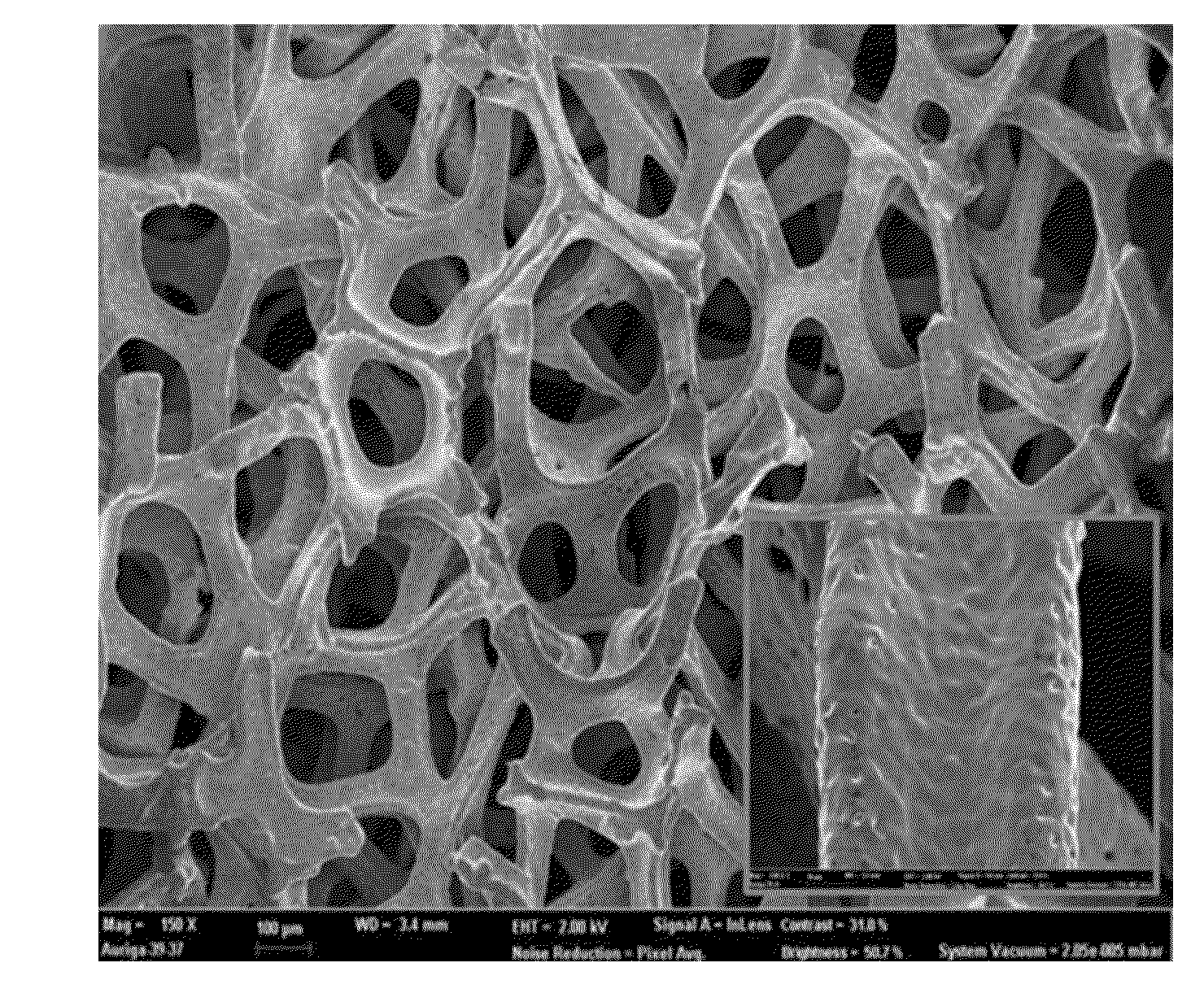
[0069]FIG. 3C shows a SEM micrograph of the surface of the copper foam manufactured in this example. In the embodiment of the present invention, the pore wall of the copper foam is coated with tin oxide over a wide range by using a precursor solution that is more concentrated than that of example 1, which makes relatively bright areas more noticeable.

embodiment 3

[0070]Another copper foam for use in a secondary lithium battery having the surface and inner pore wall coated with tin oxide is fabricated by the same method as in the case of example 1, except that the precursor solution (10 molar) is produced in this case by dissolving 1.127 grams of SnCl2.2H2O to form a SnO2 coating layer.

[0071]FIG. 3D shows a SEM micrograph of the surface of the copper foam manufactured in this example. The pore walls of the copper foam are coated by tin oxide over a wider range, which makes relatively brighter areas more noticeable, since the precursor solution used in this example has higher concentration than those used in examples 1 and 2. Also, the surface area is increased more because the surface of the pore wall is formed more roughly due to the higher concentration of tin oxide coating.


PUM

PropertyMeasurementUnit
pore sizeaaaaaaaaaa
weight/weightaaaaaaaaaa
diameteraaaaaaaaaa

Abstract

Using metal foams for the electrode of secondary lithium battery, preparing method thereof, and secondary lithium battery including the metal foam. A metal foam is used in an electrode of secondary lithium battery where the surface and the inner pore walls are coated with the active materials, a method of manufacturing such metal foam, and secondary lithium battery including the metal foam.

Description

CROSS-REFERENCE TO RELATED APPLICATIONS[0001]This patent application claims the benefit of Republic of Korea patent application 2013-0043750, filed Apr. 19, 2013, granted as Korea patent 10-1353262 on Jan. 14, 2014, which are incorporated by reference, along with an English translation of the Korean application, and along with all other references cited in this application.BACKGROUND OF THE INVENTION[0002]Several different types of secondary batteries are widely used and are commercially applicable as a rechargeable electrochemical energy storage system. Among these secondary batteries, a secondary lithium battery provides advantages in high performance due to the high power capacity and energy density. The use of the secondary lithium battery is important in portable electronic devices such as mobile phones, laptops, digital cameras, and video camcorders. In addition, a secondary lithium battery is a great power source for automotive, hybrid cars, and electric bicycles (e-bikes), w...

Claims


Application Information

Patent Timeline
Patent Type & Authority Applications(United States)
IPC IPC(8): H01M4/36H01M4/505H01M4/131H01M4/58H01M4/133H01M4/46H01M4/54H01M4/134H01M4/38H01M4/587H01M4/04B22F3/22B22F3/11B22F3/24H01M4/525
CPCH01M4/366B22F2003/247H01M4/505H01M4/131H01M4/5825H01M4/133H01M4/466H01M4/54H01M4/134H01M4/386H01M4/587H01M4/387H01M4/0404H01M4/0471B22F3/222B22F3/1121B22F3/24H01M2004/028H01M2004/027H01M4/525B22F2998/10C22C1/0408C22C1/0416C22C1/0425C22C1/0433C22C1/0466C22C33/02H01M4/0445H01M4/1391H01M4/1393H01M4/1395H01M4/661H01M4/808H01M10/052H01M10/0525Y02E60/10B22F3/10H01M4/80
Inventor UM, JI HYUNPARK, HYEJICHOI, MYOUNGGEUNCHOI, HYELIMCHO, YONG-HUNSUNG, YUNG-EUNCHOE, HEEMAN
Owner CELLMO MATERIALS INNOVATION INC
Why Eureka
Eureka Blog
Learn More