
Si-Based-Alloy Anode Material

Active Publication Date: 2014-12-18
SANYO SPECIAL STEEL COMPANY
View PDF3 Cites 22 Cited by
  • Summary
  • Abstract
  • Description
  • Claims
  • Application Information

AI Technical Summary

Benefits of technology

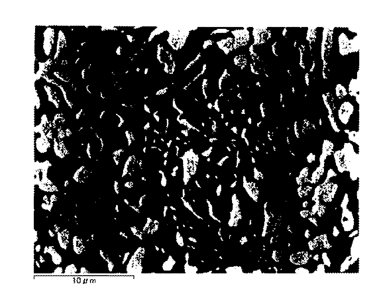
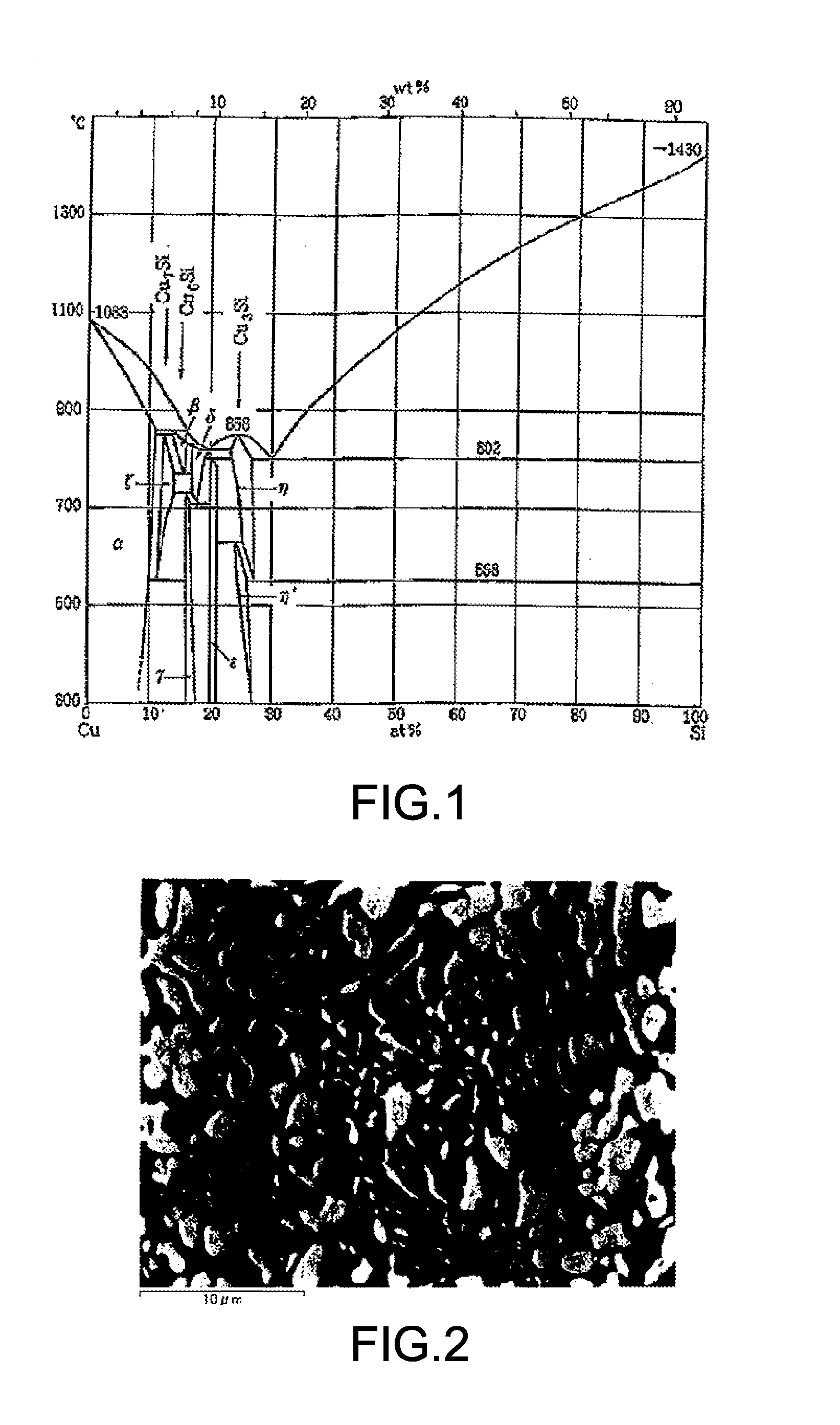
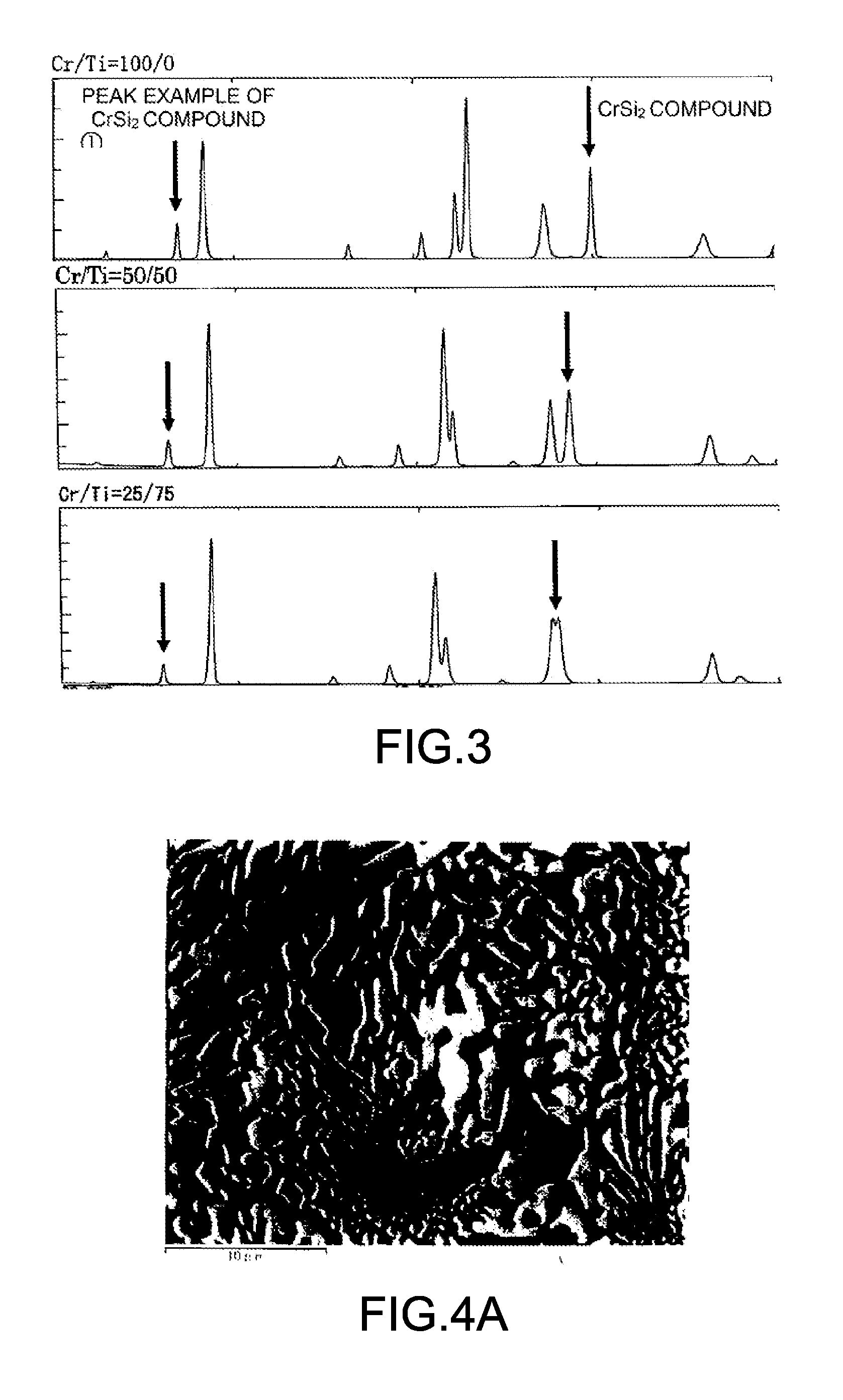
The present invention provides a Si-based alloy anode material with superior charge-discharge properties for electricity storage devices, such as lithium-ion batteries and hybrid capacitors. The inventors found that by controlling the composition, structure, and size of the Si phase and intermetallic compound phase in the Si-based alloy, they could provide an anode material with large charge-discharge capacity and long cycle life. The inventors also found that by forming a microstructure with a small average minor axis width of the Si phase, they could prevent micronization and detachment of Si from the electrode. The Si phase is surrounded by a compound phase comprising Si and one or more additional elements, which alleviates stress caused by volume expansion during lithium absorption / desorption and prevents collapse of the electrode and electrical isolation of Si. The compound phase also plays a role in improving the suppression of electrode expansion and the charge-discharge cycle characteristics. The Si-based eutectic alloy provides a solution for solving the problem of sudden drop in discharge capacity associated with cycles caused by electrical isolation of Si. The anode material has superior effects in both charge-discharge capacity and cycle life.

Problems solved by technology

In addition, there is a problem that it is industrially cumbersome to control the coating film thickness and the like.
In terms of structure, however, there is a problem that it is impossible to attain a Si phase size enough to prevent the Si phase from being micronized.

Method used


Image

  • Si-Based-Alloy Anode Material
  • Si-Based-Alloy Anode Material
  • Si-Based-Alloy Anode Material

Examples


examples

[0067]The present invention will be specifically described with reference to the following examples.

[0068]Anode material powders with the compositions shown in Table 1 were prepared by a single-roll method, a gas atomizing method or a disc-atomizing method as described below. In a liquid quenching method which is the single-roll method, a raw material with the predetermined composition was put into a silica tube with pores at the bottom, and then subjected to high frequency melting in Ar atmosphere to form molten metal, which was tapped onto the surface of a rotating copper roll, of which quenching effect was utilized to prepare quenched ribbons having an amorphous Si phase formed therein. The quenched ribbons thus prepared were put into a pot made of zirconia with zirconia balls and then sealed in Ar atmosphere, followed by pulverization by mechanical milling.

[0069]In the gas atomizing method, a raw material with the predetermined composition was put into a silica crucible with por...


PUM

PropertyMeasurementUnit
Lengthaaaaaaaaaa
Compositionaaaaaaaaaa
Structureaaaaaaaaaa

Abstract

Disclosed is a Si-based alloy anode material for lithium ion secondary batteries, including an alloy phase with a Si principal phase including Si and a compound phase including two or more elements, which includes a first additional element A selected from Ti, V, Cr, Mn, Fe, Co, Ni, Cu, Zr, Nb and Mg and a low-melting second additional element B selected from S, Se, Te, Sn, In, Ga, Pb, Bi, Zn, Al. This compound phase includes (i) a first compound phase including Si and the first additional element A; a second compound phase including the first additional element A and the second additional element B; and one or both of a third compound phase including two or more of the second additional elements B and a single phase of the second additional element B.

Description

CROSS-REFERENCE TO RELATED APPLICATIONS[0001]This application claims priorities to Japanese Patent Application No. 2012-19622 filed on Feb. 1, 2012 and to Japanese Patent Application No. 2012-276615 filed on Dec. 19, 2012, the entire disclosures of which are incorporated herein by reference.TECHNICAL FIELD[0002]The present invention relates to Si-based alloy anode materials with superior electrical conductivity, for electricity storage devices such as lithium ion secondary batteries and hybrid capacitors in which lithium ions move during charging and discharging.BACKGROUND ART[0003]In recent years, with the spread of mobile devices, high-performance secondary batteries including lithium ion batteries have been actively developed. In addition, as stationary electricity storage devices for cars and for home use, hybrid capacitors in which lithium ion secondary batteries and reaction mechanism thereof are applied to an anode have been actively developed. As anode materials in the elect...

Claims


Application Information

Patent Timeline
IPC IPC(8): H01M4/38H01M10/0525
CPCH01M4/386H01M10/0525H01M2220/10H01M2220/20H01M2220/30H01M10/052H01M2004/027C22C9/00C22C9/02C22C9/04C22C28/00H01M4/134Y02E60/10H01M4/13H01M4/38H01M4/46
Inventor HIRONO, TOMOKIKARIYA, TETSUROSAWADA, TOSHIYUKI
Owner SANYO SPECIAL STEEL COMPANY
Learn More