Controlled Thin Film Vapor Generator for Liquid Volume Reduction

a thin film vapor generator and liquid volume technology, applied in vacuum distillation separation, waste water treatment from quaries, separation processes, etc., can solve the problems of corrosion, heat transfer surface evaporate surface scaling, and unwanted drying and scaling about the heat transfer surface, so as to reduce the energy consumption and increase the thermal energy

Inactive Publication Date: 2014-12-18
R3 FUSION
View PDF3 Cites 12 Cited by
  • Summary
  • Abstract
  • Description
  • Claims
  • Application Information

AI Technical Summary

Benefits of technology

[0028]Vapor generated from processing the fluid within the first vessel may, in an embodiment, be subsequently directed into a heat jacket situated about the second vessel in order to minimize energy consumption required to heat the second vessel. In an embodiment, the generated vapor may be compressed, and therefore provided with increased thermal energy, prior to being directed into the heat jacket about the second vessel. In an embodiment, the processed fluid may be preheated by processed fluid from the second vessel. In another embodiment, the processed fluid may be preheated by a heat exchange fluid from a heat jacket situated about the second vessel.

Problems solved by technology

A common problem in chemical reaction processes is how to achieve the proper hydrodynamics in the reactor to efficiently produce the desired products.
In evaporators, for example, non-uniform evaporation of a fluid against the heat transfer surface causes unwanted drying and scaling about the heat transfer surface.
In extreme cases, the reduction in the film thickness creates a dry spot, which eventually results in scaling of the heat transfer surface evaporate surface and corrosion.

Method used


Image

  • Controlled Thin Film Vapor Generator for Liquid Volume Reduction
  • Controlled Thin Film Vapor Generator for Liquid Volume Reduction
  • Controlled Thin Film Vapor Generator for Liquid Volume Reduction

Examples


Embodiment Construction

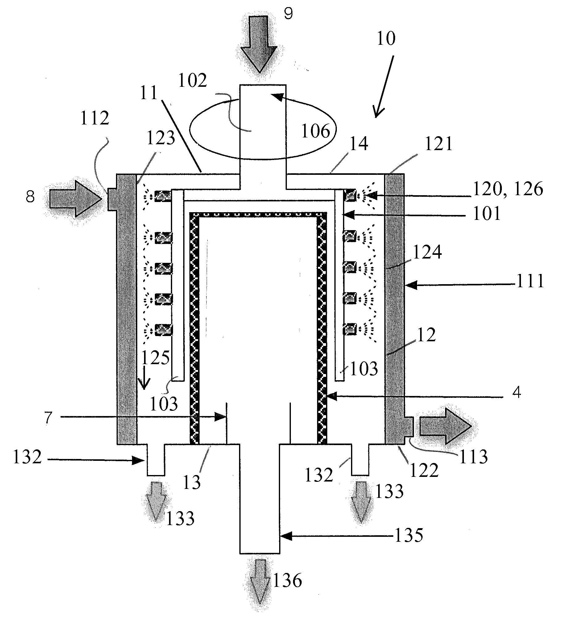
[0037]Embodiments of the present disclosure generally provide a reactor 10 for processing a fluid, and various methods for processing a fluid.

Reactor 10

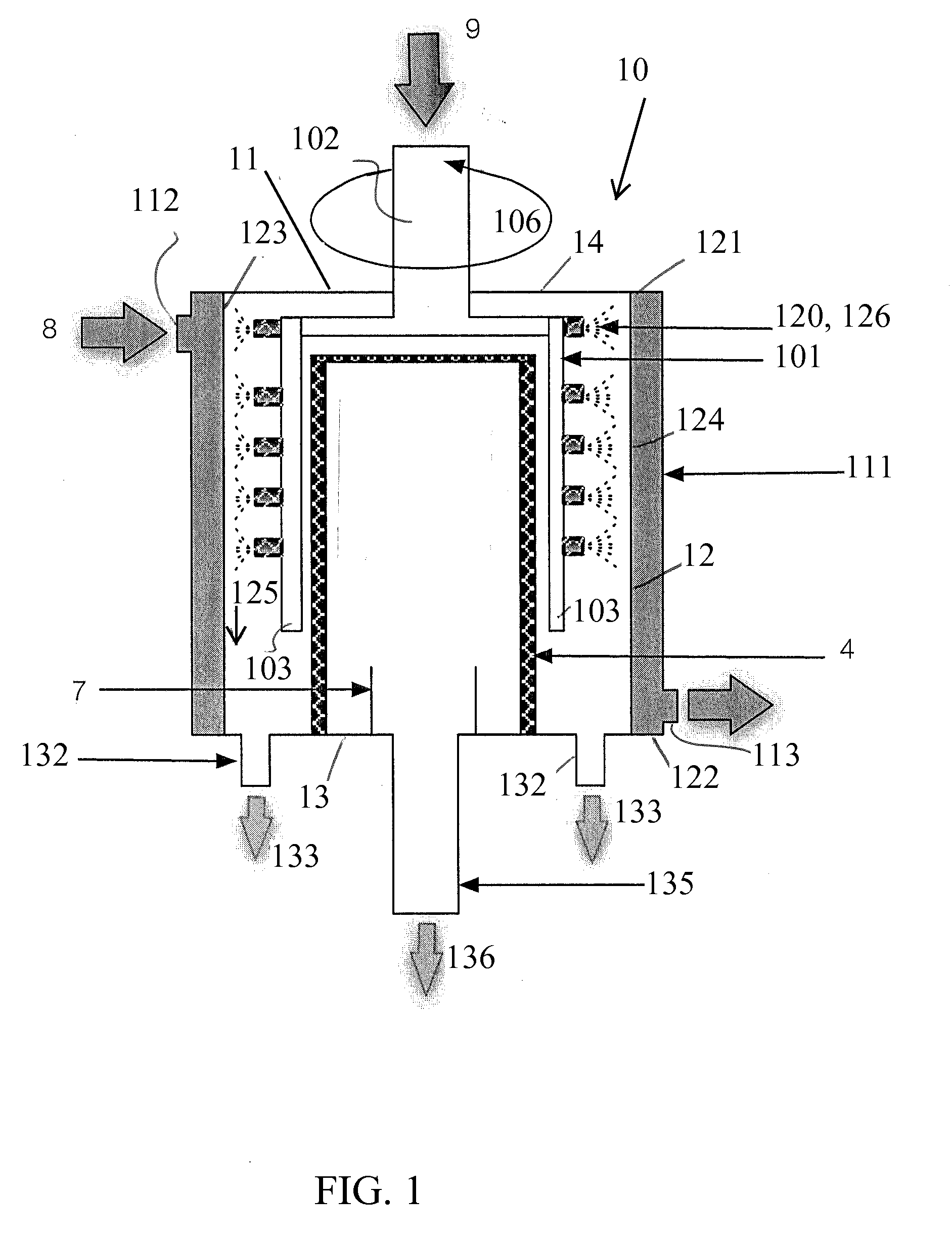
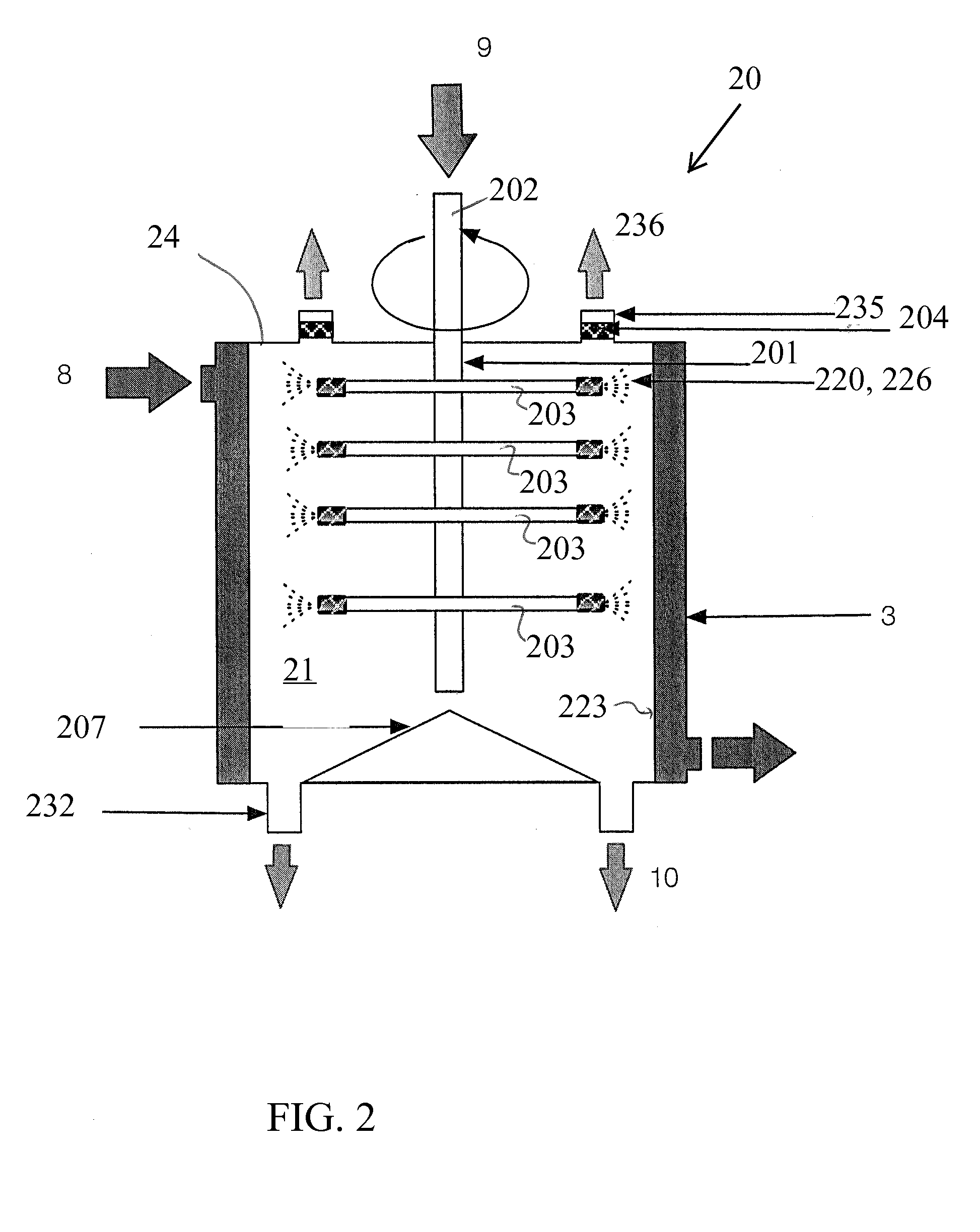
[0038]FIGS. 1-3 illustrate representative configurations of reactors 10, 20, 30, and parts thereof. It should be understood that the components of reactors 10, 20, 30, and parts thereof shown in FIGS. 1-3 are for illustrative purposes only, and that any other suitable components or subcomponents may be used in conjunction with or in lieu of the components comprising reactors 10, 20, 30, and the parts of reactors 10, 20, 30, described herein.

[0039]Looking now at FIG. 1, in accordance with one embodiment, there is illustrated a reactor 10 for, among other things, continuous processing, for example, controlled, uniform, thin film vapor generation for liquid volume reduction. As illustrated, reactor 10 includes a vessel 11 for accommodating fluids to be processed. The vessel 11, in an embodiment, includes a body portion 12 within which a...


PUM

PropertyMeasurementUnit
thicknessaaaaaaaaaa
thicknessaaaaaaaaaa
lengthaaaaaaaaaa

Abstract

A reactor comprising a vessel; a fluid dispensing system having a plurality of ports arranged lengthwise along the inner surface of the vessel to distribute the fluid thereon in a controlled manner to maintain substantially uniform thin film flow along the length of the inner surface; and an outlet for removing vapor. A system comprising a fluid source; a first vessel; a heat exchanger for preheating the fluid; a first pathway for directing a preheating fluid from the first vessel to the heat exchanger; and a second pathway for directing preheated fluid toward the first vessel for processing. A method comprising introducing a fluid; distributing the fluid in a controlled manner to form a substantially uniform thin film flow an inner surface of a vessel; evaporating fluid; and removing vapor. A method comprising introducing a fluid; processing the fluid; directing processed fluid into another vessel; and further processing the fluid.

Description

CROSS-REFERENCE TO RELATED APPLICATION[0001]This application claims priority to U.S. Provisional Patent Application No. 61 / 836,640, entitled “Controlled Thin Film Vapor Generator For Liquid Volume Reduction,” filed on Jun. 18, 2013, which is hereby incorporated by reference for all purposes.TECHNICAL FIELD[0002]The present invention relates to processing reactors, and more particularly, to continuous processing reactors that can impart fluid being processed with high heat transfer and high transport rates. The present invention relates, in particular, to the use of thin film heat transfer for producing vapors, which can be vented, condensed or compressed and can act as a continuous source for the generation of vapor, and for continuous evaporation or distillation of fluids.BACKGROUND[0003]A common problem in chemical reaction processes is how to achieve the proper hydrodynamics in the reactor to efficiently produce the desired products. In evaporators, for example, non-uniform evapo...

Claims


Application Information

Patent Timeline
Patent Type & Authority Applications(United States)
IPC IPC(8): B01D1/00C02F1/08B01D3/00B01D1/22B01D1/28
CPCB01D1/0064B01D1/22B01D1/28C02F2103/10C02F1/08C02F2103/06C02F2103/08B01D3/007B01D1/16B01D1/223B01D1/305Y02A20/124
Inventor JACHUCK, ROSHAN J.J.
Owner R3 FUSION
Why Eureka
Try Eureka